
Doppler Navigation Radar

Figure 1: Geometry of a Doppler navigation radar in the X configuration

Figure 1: Geometry of a Doppler navigation radar in the X configuration
Doppler Navigation Radar
A Doppler navigation radar is a navigation aid used in aviation. It measures ground speed and any drift angles independently of wind speed and direction.
These radar systems consist of up to four unmodulated continuous wave radar sets, which exclusively measure Doppler frequencies and compare them with each other. The system with four antenna patterns within a rectangle is called an “X configuration.” In the “λ configuration,” one of the rear patterns is omitted.
The radiation angles must all be aligned at the same angle from the plumb line. The speed over ground is calculated by comparing the Doppler frequencies of the front diagrams with the rear diagrams. The comparison of diagram 1 and diagram 2 gives the drift.
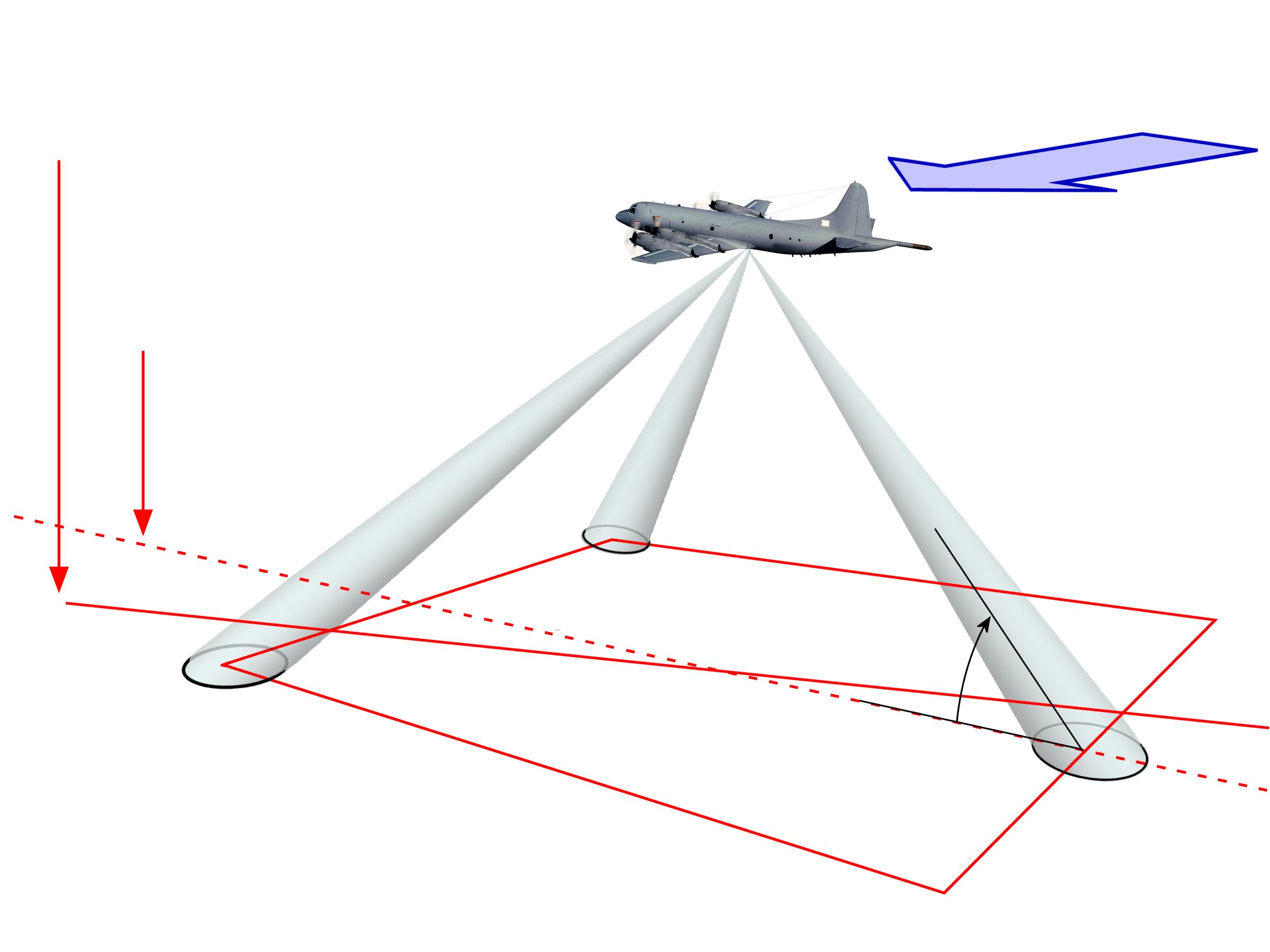
Figure 2: Geometry of a Doppler navigation radar in the Y configuration
Figure 2: Geometry of a Doppler navigation radar in the Y configuration
In the so-called Y configuration, the rearward-facing radiation pattern (3) is used to directly measure the speed over ground. The radial speed measured by the continuous wave radar can be converted into the actual speed over ground using a trigonometric function.
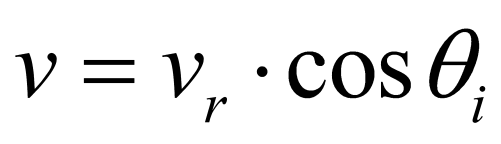

(1)
The angle of incidence θi represents the center of the beam of the radar antenna. This is calculated from the tilt of the antenna specified during antenna installation and the pitch angle of the aircraft. (This is because the aircraft does not fly horizontally in the air — it requires a pitch angle that is aerodynamically favorable for the density of the air at the flight altitude.) For the X configuration, the radial speed vr is calculated from the arithmetic mean of the results from diagrams 3 and 4 or 1 and 2.
angle
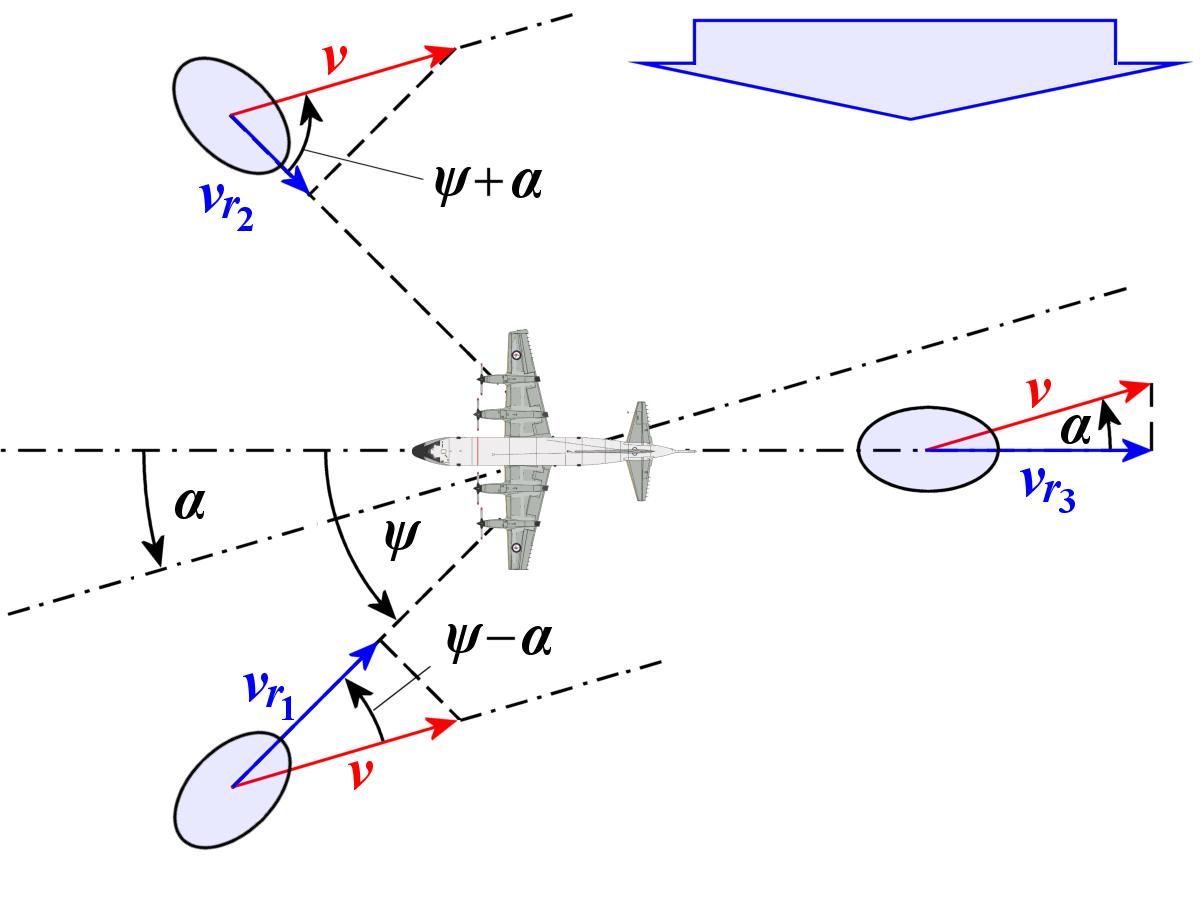
Figure 3: Top view: projection of angles and vectors

The two radiation directions 1 and 2 provide the speed information according to Figure 3:


(2)
In fact, radiation directions 1 and 2 would therefore be sufficient for calculating the speed over ground and the drift angle. In practice, however, radiation direction 3 (or 3 and 4) is also used to compensate for a change in the pitch angle due to climbing or descending by comparing the values measured forward with those measured backward.
The accuracy of speed measurement achievable with this method is approximately 0.5% over land and approximately 0.7% over water. The slight deterioration in accuracy over water is caused by an additional Doppler frequency due to the movement of ocean waves.
In older strategic attack aircraft, this system was used to maintain course over the Atlantic or Pacific despite wind conditions. Modern aircraft with GPS no longer require such a navigation aid. However, the same principle can be applied in reverse for remote sensing of the Earth and can be used to measure local wind and wave directions on oceans.