
Precipitation Radar

Figure 1: Precipitation radar of the Deutscher Wetterdienst (German Weather Service) in Essen-Bredeney
(51°24’20,5" N 6°58’01,6"E)
Figure 1: Precipitation radar of the Deutscher Wetterdienst (German Weather Service) in Essen-Bredeney
(51°24’20,5" N 6°58’01,6" E)
How does the precipitation radar work?
Precipitation Radar
A precipitation radar is a weather radar operating in the S band or C band (less frequently in the X band because of higher attenuation). It usually has a symmetrical parabolic antenna that can rotate and change its elevation angle. In the X band, an antenna array of slotted waveguide antennas may also be used. The radar operates according to the pulsed radar principle to achieve long ranges. Contrary to a common misconception, a precipitation radar does not measure the size of clouds.
A precipitation radar can determine the following quantities:
- The backscattering properties (reflectivity) of precipitation particles (“hydrometeors”), from which the precipitation rate can be estimated. Radar is therefore used to locate precipitation areas and to measure precipitation quantitatively. Precipitation amounts can be calculated by integrating the measured precipitation rate over time at a given location on the ground. With suitable assumptions, reflectivity measurements can also be used to estimate the vertically integrated liquid water content of a precipitation cloud.
- By comparing signals from two pulse repetition intervals, a Doppler frequency can be measured. It indicates the distribution of radial velocities of the raindrops relative to the radar. The radial wind velocity can then be determined. By comparing these velocities during one antenna rotation, the horizontal wind velocity can be derived.
- Most modern precipitation radars transmit both horizontal (H) and vertical (V) polarization components, using dual polarization. The returning echoes are analyzed for differences in reflectivity, the coherence between the H and V signals, and their phase difference. This provides additional information about the size, shape, and type of precipitation particles. It therefore helps distinguish rain, snow, and hail.
Most modern precipitation radars provide three-dimensional measurements. After each rotation, the antenna changes its elevation angle, scanning the surrounding area at different elevations (elevation scans). This produces a so-called volume scan which, compared with an air traffic control radar, is updated relatively slowly, usually every 5 to 15 minutes (depending on the number of elevation angles and the required accuracy). The German Weather Service (DWD) completes a full cycle every five minutes.

reflector
transducer
conductor
Figure 2: Schematic representation of a weather radar under a radome


Technical specifications
Precipitation radar generally uses a short, narrowband transmitted pulse generated by a high-power vacuum tube (magnetron or klystron). A magnetron transmitter is considerably less expensive than a klystron transmitter, but has the disadvantage that the radar can only be pseudo-coherent rather than fully coherent, making Doppler-frequency measurements less accurate. Solid-state transmitters are also possible, but their peak pulse power is lower because of the limited voltage-handling capability of semiconductors. The resulting need to use wider-bandwidth intrapulse-modulated transmitted pulses also reduces measurement accuracy because of their time sidelobes. Receiver sensitivity is also limited because a wider-bandwidth receiver collects more noise.
Radar antenna
The radar antenna is usually a reflector antenna with a parabolic reflector that produces a symmetrical antenna pattern. The beamwidth is usually about one to two degrees. Depending on the frequency band, the reflector diameter is between 40 and 80 times the wavelength. The antenna is fed by a horn feed. An orthomode transducer allows dual-polarization radars to transmit horizontal and vertical polarization simultaneously or alternately.

Figure 3: Because electromagnetic waves diverge, the pulse volume increases with distance, so measurements at shorter ranges are more precise.

Figure 3: Because electromagnetic waves diverge, the pulse volume increases with distance, so measurements at shorter ranges are more precise.
Transmission frequency or wavelength
A network of radar stations is needed to cover a large area; the number of stations depends on the effective range of each radar. However, the accuracy of precipitation radar measurements decreases with increasing range (see the pulse volume in Figure 3). The choice of wavelength also depends on the cost of the radar equipment, the required coverage, and the prevailing type of precipitation. At long ranges, the curvature of the Earth becomes important because weather phenomena at lower altitudes disappear below the horizon.
In tropical and subtropical regions, where weather radar networks are often less densely developed, radars operating in the S band are commonly used. Their long range makes it possible to monitor large areas with relatively few radar sites. They can achieve ranges of up to 800 km, which can actually be reached under special atmospheric propagation conditions (ducting). S-band radars are relatively expensive, but their wavelengths undergo only slight attenuation even in very heavy rain and hail. This makes them especially suitable for regions affected by intense thunderstorm systems, such as tropical cyclones and tornadoes. Their peak transmitting power is in the megawatt range. Under normal propagation conditions, beyond about 250 km the radar can detect precipitation only at very high altitudes due to the curvature of the Earth. At 800 km, it is therefore mainly useful for identifying major storm cells at altitudes above 15 km.
In Europe, where weather radar networks are well developed and the climate is generally temperate, radars operating in the C band are widely used. This frequency range provides higher accuracy. Their maximum range is approximately 250 km, although only 150 to 180 km is commonly used to obtain more accurate measurements. C-band radars are less expensive, but their wavelength is attenuated by heavy rainfall. This is acceptable in temperate climates, where precipitation is usually light to moderate. However, their performance is poorer during intense summer thunderstorms. The peak power of their transmitted pulses is usually 250 kW.
Receiver sensitivity and receiver dynamics
Technically, receiver sensitivities below −100 dBm are possible. These receivers can process echoes with powers of less than one tenth of a picowatt. At these levels, background noise is particularly troublesome. To minimize losses in the antenna feeder lines, the receivers are placed as close to the antenna as possible.
At the same time, extremely strong echo signals must also be processed. To achieve the required linear receiver dynamic range of up to 105 dB, several receivers with different sensitivities operate in parallel. The software selects the signal with the best signal-to-noise ratio that is not yet overloaded.
Pulse repetition frequency
Modern precipitation radars can vary both their antenna rotation speed and pulse repetition frequency. Since most weather occurs in the troposphere, whose upper boundary lies at approximately 8 to 18 km depending on latitude, the altitude range that needs to be scanned is limited. Therefore, steep elevation angles do not have to be scanned out to the maximum range of 250 km. At high elevation angles, interference from stationary targets is also negligible. The risk of interfering range ambiguities caused by precipitation is lower as well. This allows a much higher pulse repetition frequency and faster antenna rotation than at lower elevation angles.

Figure 4: Scan strategy for a precipitation radar
(The vertical scale is exaggerated by a factor of five, making steeper angles appear narrower, although they have the same beamwidth.)

Figure 4: Scan strategy for a precipitation radar
(The vertical scale is exaggerated by a factor of five, making steeper angles appear narrower, although they have the same beamwidth.)
Scanning strategy
A scanning strategy is illustrated in Figure 4. Each cycle begins with a precipitation scan whose antenna elevation angle depends on the site’s horizon and local obstructions. During this rotation, the radar uses a pulse repetition frequency of 600 Hz, corresponding to a maximum unambiguous range of 250 km, although only 150 km is used. The antenna rotates at 12° per second (≙ 2 min⁻¹). The volume scan then begins at an elevation angle of 5.5° and steps down by one degree after each rotation. These scans use pulse repetition frequencies of 600 or 800 Hz. The antenna rotation speed increases slightly to 18° per second (≙ 3 min⁻¹); only the lowest elevation scan again uses 12° per second to improve the suppression of stationary clutter. During the eighth rotation, the scan is performed at an elevation angle of 8° with a pulse repetition frequency of 800 or 1 200 Hz. Elevation angles of 12°, 17°, and 25° use 2 410 Hz at a rotation speed of 30° per second (≙ 5 min⁻¹). Finally, the radar scans vertically upwards for internal calibration. The antenna then turns to the north and waits for the start of the next cycle. All DWD precipitation radars begin their next cycle simultaneously. This approximately synchronizes their antenna rotations and reduces the risk of mutual interference. It also supports the creation of composite radar products (radar images calculated by combining data from several radar stations), because, for example, the data from each precipitation scan are recorded within the same minute.

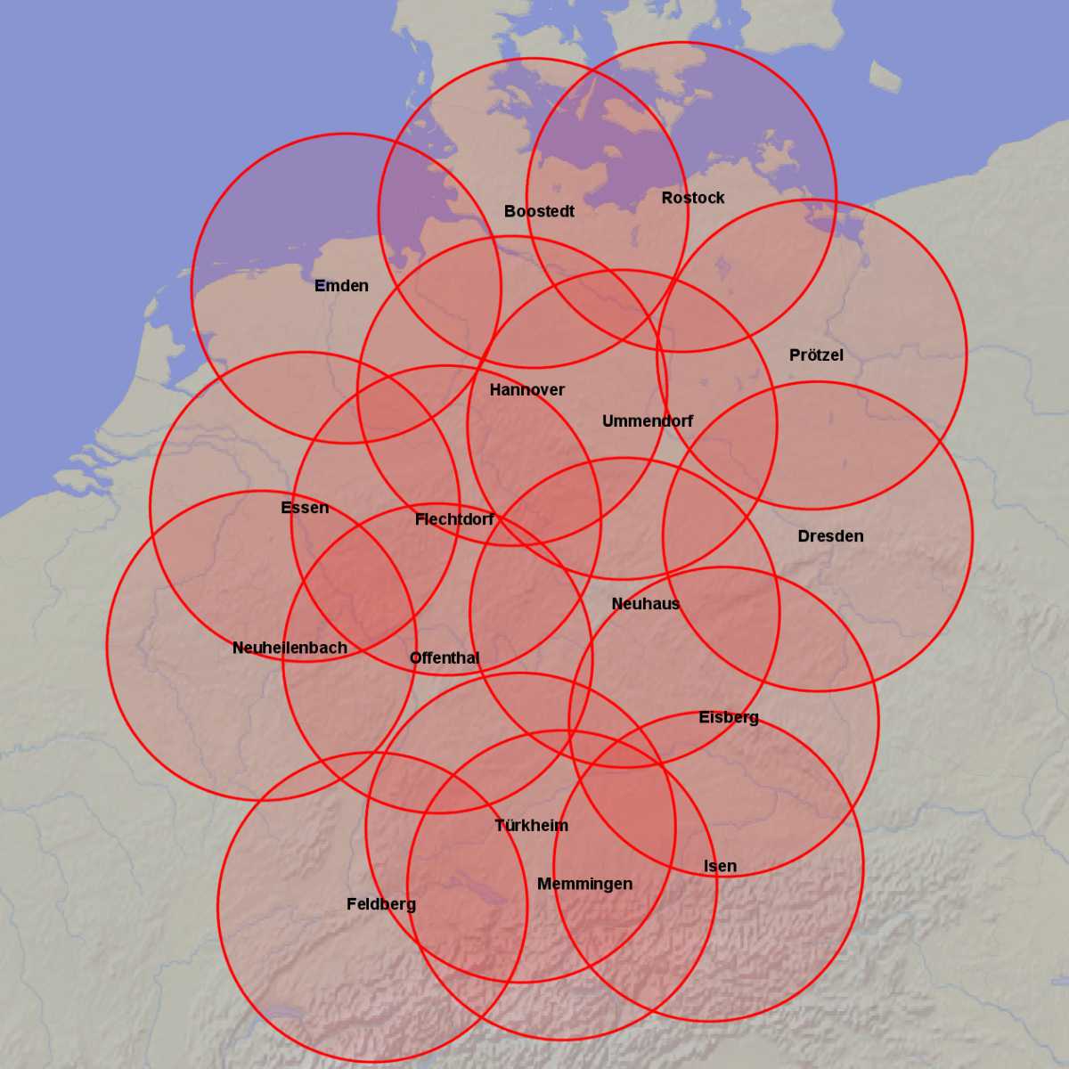
Figure 5: Horizontal radar coverage of a network of weather radars in Germany (Source: Deutscher Wetterdienst)
Figure 5: Horizontal radar coverage of a network of weather radars in Germany (Source: Deutscher Wetterdienst)
Radar Distribution
The Deutscher Wetterdienst (German Weather Service, DWD) operates a network of 17 precipitation radars distributed across Germany to cover the entire country. Their coverage areas overlap in places, so data from neighboring radar stations can be used if one station fails. One radar in the network is transportable and can be moved to another site during lengthy planned outages.
Overview of weather radars presented on the radar tutorial.