
Matched Filter
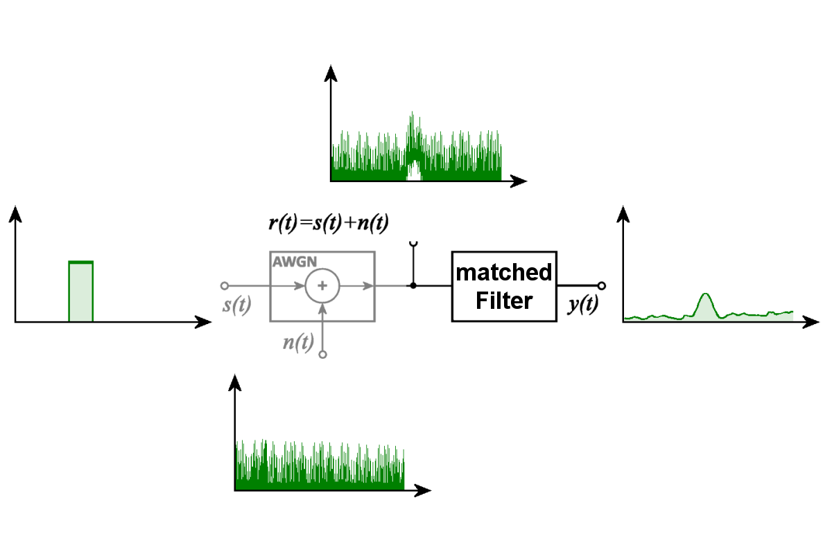
Figure 1: A matched filter enhances a known signal in additive white Gaussian noise (AWGN).
Matched Filter
A matched filter (also called an optimum filter) is a filter designed to match a particular signal waveform that is assumed to be known. It is used to detect such a signal even when the signal is obscured by noise. Under specified conditions, it maximizes the signal-to-noise ratio (SNR) at the filter output at a particular sampling instant. This optimality applies to the assumed signal waveform in the presence of additive white noise. A matched filter can also be used to determine the time position and, under appropriate conditions, the amplitude of a received signal.
 Video Version
Figure 1 illustrates this principle using an idealized example. A known rectangular pulse s(t) is superimposed with a noise signal n(t). The noise is assumed to be additive white Gaussian noise (AWGN). The resulting received signal r(t) therefore contains both the original pulse and the noise. The pulse is barely distinguishable in the noisy signal waveform. After processing by the matched filter, however, a distinct peak appears at the filter output. The noise is not completely removed; instead, the known signal is enhanced relative to the noise background.
Operating Principle of a Matched Filter
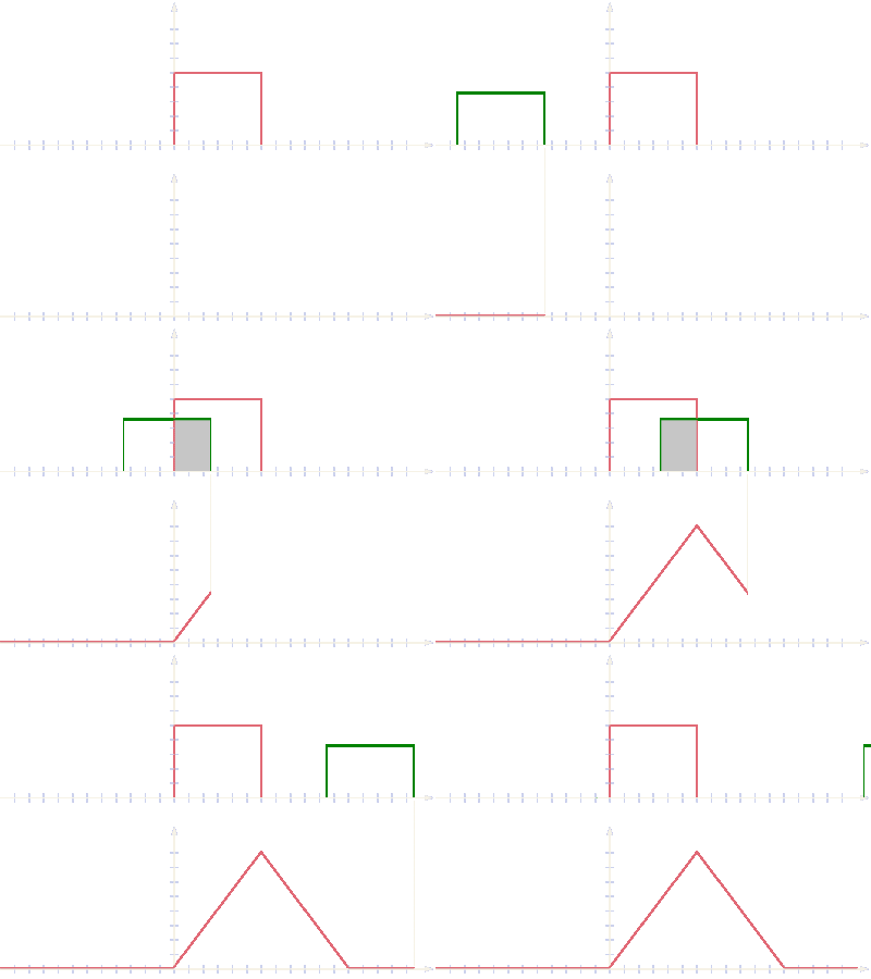
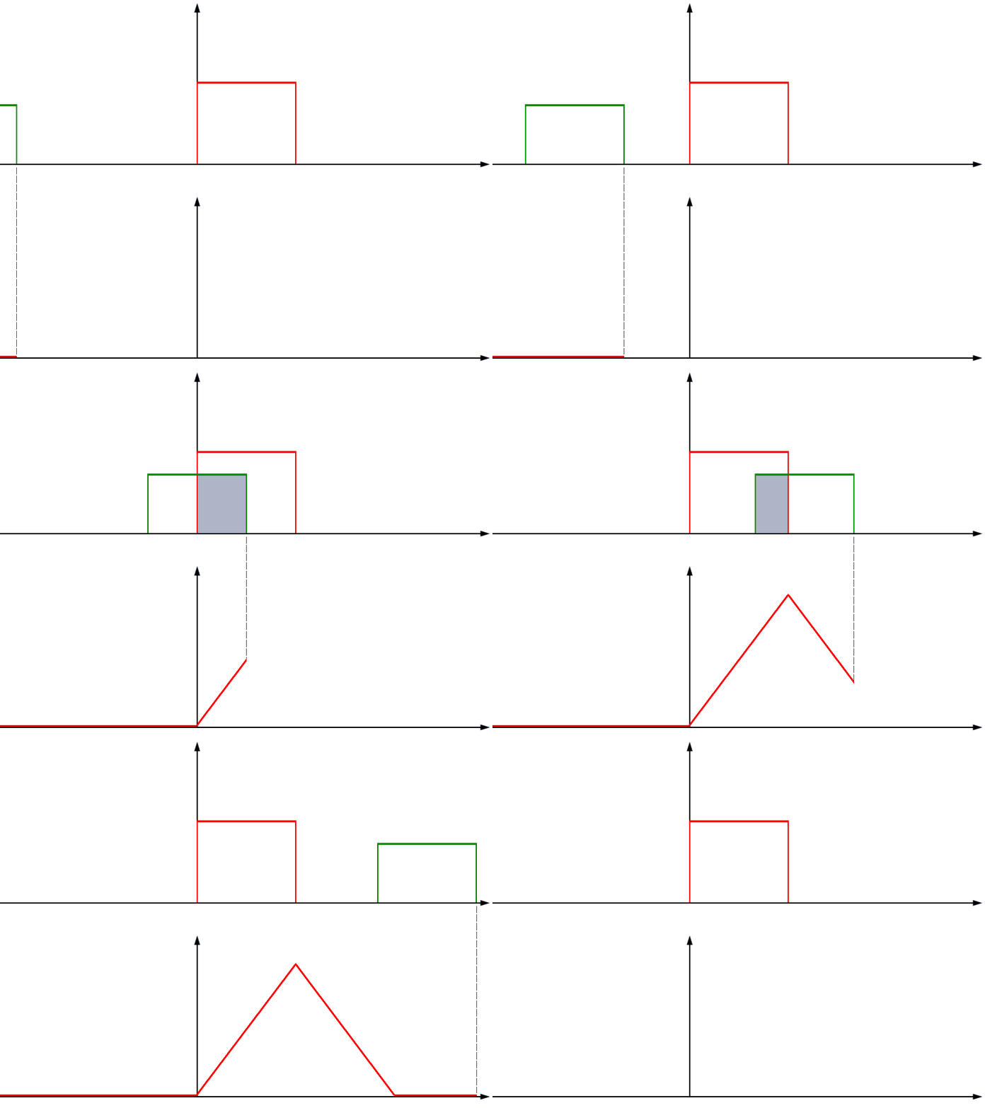
The operation of a matched filter is based on comparing a received signal with a known signal waveform. For this purpose, the received signal is filtered using a time-reversed version of the reference signal, which is also complex-conjugated in the case of complex signals. This operation is equivalent to cross-correlation. During the calculation, the relative time positions of the two signals are shifted, and a correlation value is determined for each time shift.
Figure 2A simple thought experiment illustrates this process using an ideal rectangular pulse. As long as two identical rectangular pulses do not overlap in time, there is no contribution to their correlation. As their overlap increases, the correlation value increases. It reaches its maximum when the pulses are perfectly aligned in time. The value then decreases as one pulse is shifted further. Therefore, the correlation response of two identical ideal rectangular pulses has a triangular shape.
For more complex signal waveforms, the comparison follows the same mathematical principle. The correlation peak indicates the time shift at which the received signal best matches the assumed signal waveform. This time shift can be used, for example, to determine the propagation time of a radar echo. At the same time, the energy of the known signal component is combined to obtain the most favorable signal-to-noise ratio under the assumed conditions. However, this does not mean that all other properties of the received signal are also evaluated optimally.
Why Is the Waveform of a Radar Echo Unknown?
In a radar system, the waveform of the transmitted signal is known. However, the waveform of the actual received echo is generally unknown. If the echo were simply a delayed and attenuated copy of the transmitted signal, the filter could be optimally matched to that known waveform. With real radar targets, however, reflection and propagation modify the transmitted signal.
These modifications contain precisely the information that a radar is intended to obtain about a target. Information about target motion, for example, may be expressed as a Doppler frequency shift. Different scattering centers on an extended target may produce partial reflections with different time delays, thereby changing the pulse shape and duration of the echo signal. The phase, amplitude distribution, and polarization of the received wave may also differ from those of the transmitted signal.
Additional effects may result from multipath propagation, interference between partial reflections, time-varying reflection characteristics, or the motion of individual parts of the target. A received radar echo may therefore consist of several signal components with different propagation delays, amplitudes, phases, and Doppler frequencies. Which of these characteristics are important for signal processing depends on the particular task of the radar system.
The target information obtained from these differences is discussed in more detail in the chapter Information Content of Radar Signals. This creates a fundamental problem for the matched filter: a filter can be optimally matched to only one particular assumed signal waveform. If the actual echo differs from this waveform, the original matching conditions are no longer fully satisfied.
Effects of Doppler Frequency
One particularly important influence is the Doppler effect. The radial velocity of a target changes the frequency of the received echo signal. With a modulated transmitted pulse, this frequency shift may cause the time-dependent phase relationships of the received signal to differ from the waveform assumed by the filter. As a result, the correlation peak may decrease in amplitude or shift in time.
The extent to which a Doppler frequency affects the result depends on the waveform used and the signal duration. Some waveforms are relatively insensitive to Doppler shifts. With other waveforms, even small frequency deviations cause significant changes in the output response of the matched filter. This relationship between time delay and Doppler frequency is described by the ambiguity function.
The problem becomes particularly apparent in helicopter recognition. The echo signal contains more than the Doppler frequency caused by the radial velocity of the helicopter as a whole. The rotating rotor blades generate additional time-varying Doppler components known as micro-Doppler. The resulting echo therefore does not have a single Doppler frequency to which an individual matched filter could readily be optimally matched.
One possible solution is to use several matched filters designed for different assumed Doppler frequencies. Each filter processes the same received signal but is matched to a different frequency shift. This makes it possible to determine which filter, among the assumptions being tested, provides the best match to the echo signal.
Filter Banks and Parallel Signal Processing

circuit
Figure 3: Parallel arrangement of several matched filters

circuit
Figure 2: Parallel arrangement of several matched filters
Figure 3Figure 2 shows a parallel arrangement of several matched filters. Each filter is matched to a particular variation of the expected signal waveform, for example, to a different Doppler frequency. The output signals are then compared. A subsequent Greatest-Of circuit can select the output signal with the highest value according to the evaluation criterion used.
However, the highest output amplitude does not necessarily indicate the best signal-to-noise ratio under all circumstances. This is particularly true when the noise powers or gains of the individual filter branches differ. For a meaningful comparison, the filter outputs must therefore be appropriately normalized or evaluated using a common detection criterion.
Modern radar systems can use a large number of such filters simultaneously. Because the required filtering operations are relatively easy to implement using digital signal processing, filter banks are now frequently implemented in software or with digital signal processors. Therefore, the arrangement shown in the figure does not necessarily require a corresponding number of separate analog filter modules.
Matched Filters in Pulse Compression

Figure 4: Schematic diagram of a pulse compression circuit – an example of a matched filter

Figure 3: Schematic diagram of a pulse compression circuit – an example of a matched filter
Figure 4: Schematic diagram of a pulse compression circuit – an example of a matched filter
An important application of the matched filter is pulse compression. This technique uses a longer transmitted pulse whose frequency or phase changes according to a known modulation law during the pulse. The received signal is processed by a filter matched to this modulation. The signal energy contained in the long received pulse is thereby concentrated into a relatively narrow correlation peak.
The schematic diagram in Figure 4Figure 3 illustrates one possible implementation of pulse compression. The received signal is divided into several frequency subbands. Different delays are used to align the corresponding signal components in time so that they arrive at the summing stages as nearly simultaneously as possible. For the intended signal waveform, these components combine to form a distinct output pulse. The diagram therefore illustrates one possible technical implementation of the correlation principle.
Pulse compression makes it possible to combine the advantages of greater transmitted pulse energy with good range resolution. However, this requires the waveform used for filtering to match the received signal sufficiently well. A Doppler shift or a change in pulse shape can affect the result. The extent of this effect depends on the modulation used.
For an idealized stationary point target, the received signal can approximately be regarded as a delayed and attenuated copy of the transmitted signal. This provides particularly favorable conditions for a matched filter. With moving or extended targets, however, deviations may occur that must be considered when designing the pulse compression circuit.
Mismatched Filters
Maximizing the output signal-to-noise ratio is not always the most important design objective. In pulse compression, for example, sidelobes of the correlation response can make it difficult to detect weaker targets near a strong target. Therefore, filters are sometimes used whose transfer functions intentionally differ from that of an optimally matched filter. Such filters are called mismatched filters.
A mismatched filter can be used, for example, to reduce the sidelobes of the pulse compression response. This may require accepting a loss in signal-to-noise ratio compared with the ideal matched filter. It is therefore a deliberate trade-off among different signal processing requirements, rather than simply a filter designed for an additional Doppler frequency.
Particularly stringent requirements for suppressing range sidelobes may arise in meteorological radar systems. These systems must not only detect individual targets but also measure the spatial distribution of backscatter as accurately as possible. Range sidelobes can cause strong precipitation echoes to appear in neighboring range intervals, thereby distorting the measurements. In such applications, low sidelobe power may be more important than achieving the theoretically maximum signal-to-noise ratio.
Matched Receiver
The matching principle can also be applied to the entire receiver chain. In this case, not only the characteristics of an individual filter are considered, but also factors such as the bandwidth and noise characteristics of the receiver circuitry. Different settings of the receiver bandwidth may be appropriate for different received signals.
A receiver designed in this way to match the intended signal waveform and receiving conditions is called a matched receiver. The term describes the optimization of the entire receiving system for a particular task. Here, too, matching is optimal only under the assumed signal and noise conditions.
Importance in Radar Signal Processing
The matched filter is an important method for improving the detection of weak signals in the presence of noise. Its main strength is that it uses the known time structure of an expected signal during processing. However, it cannot be optimally matched to all possible changes in an unknown echo signal simultaneously.
In practice, filter banks, different signal models, or additional processing methods are therefore used depending on the task. A distinction must be made between detecting a target as reliably as possible and extracting additional information from its echo signal. A change in the received signal may represent an undesirable mismatch for a particular matched filter, while at the same time providing valuable information about the target's characteristics or motion.
Anyone wishing to investigate the operation of a matched filter experimentally can use a matched filter simulator with various examples of input signals. Custom signal waveforms can also be investigated there.