
Direct Digital Synthesis
Direct digital synthesis (DDS) is a digital method for generating signals with virtually arbitrary waveforms and freely selectable frequencies and frequency resolution from a precise reference clock. In radar technology, this method is used to generate periodic signals with finely adjustable frequencies. Additional internal functions such as phase and/or amplitude modulation, digital filtering, and I&Q outputs can be incorporated. Digital signal processors, programmable logic devices such as FPGAs, or specialized application-specific integrated circuits (ASICs) can provide widely different output frequencies depending on the circuit architecture. The achievable output frequency and frequency resolution depend primarily on the reference clock frequency, the width of the phase accumulator, the speed of the digital-to-analog converter, and the requirements for signal quality. In radar technology, these circuits are frequently used to generate the intrapulse modulation of the transmitted signal at the intermediate-frequency stage.

address
counter
memory
D/A
converter
Figure 1: Simplified block diagram of direct digital synthesis

address
counter
memory
D/A
converter
Figure 1: Simplified block diagram of direct digital synthesis
address
counter
memory
D/A
converter
Figure 1: Simplified block diagram of direct digital synthesis
Circuit Design and Operation
The central component of the circuit is a memory containing the amplitude values of the desired output waveform for each phase angle of the oscillation. A phase accumulator determines the next phase value with every reference clock cycle. This phase value is used to address the memory, whose digital output word is converted into an analog output signal by a high-speed digital-to-analog converter. In principle, the phase accumulator is a digital accumulator to whose contents a fixed numerical value is added at every reference clock cycle. This value is called the frequency tuning word (FTW). It determines the phase increment between two successive clock pulses and therefore the frequency of the generated output signal. For a phase accumulator with a width of n bits, the following relationship applies: fout = fclock · FTW / 2n. By selecting the frequency tuning word, memory addresses can be skipped, allowing the output frequency to be adjusted in very small increments.
In many cases, the memory only needs to contain the samples of one signal period, which are then repeated cyclically. However, a sinusoidal signal with a linearly increasing frequency can also be stored over a longer interval containing many signal periods, for example, to generate a defined transmitted waveform with a linearly or nonlinearly changing frequency. Due to quantization steps, the output signal of the digital-to-analog converter contains numerous harmonics. These harmonics are removed by a subsequent low-pass filter.
From the perspective of radar technology, two different types of DDS circuits can be used:
- The most common type generates sinusoidal signals that are coherent with a fixed system clock. This has led to the development of specialized integrated circuits containing a complete circuit designed for a particular standardized waveform (for example, a linear sawtooth voltage or a sinusoidal voltage). In these circuits, the waveform is often generated by a read-only memory addressed by an internal counter.
- Another type allows virtually arbitrary waveforms to be generated. Instead of using an address counter and memory, each individual voltage step is specified by a computer program and supplied directly to a digital-to-analog converter. To reduce the processing load on the computer, the values may also be stored temporarily in rewritable memory, which is then read cyclically by an external counter.
Applications
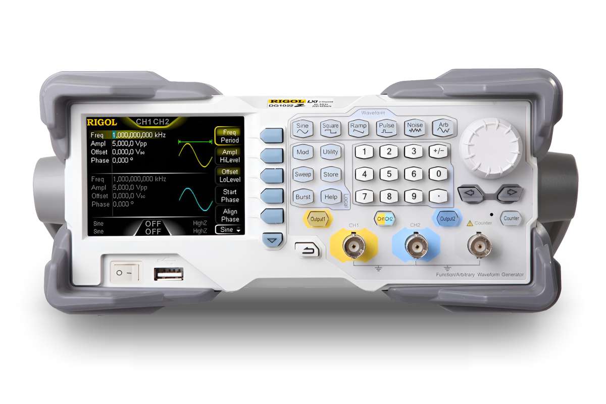
Figure 2: Rigol DG1022Z signal/arbitrary waveform generator
Digital arbitrary waveform generators use direct digital synthesis (DDS) and can generate signals with very fine frequency resolution. They assist in developing and optimizing circuits and in troubleshooting signal problems in complex electronic equipment.
Radar systems employing linear or nonlinear intrapulse modulation use this principle for transmitted signal generation. Modern radar systems can even deliberately modify the type of intrapulse modulation to improve target detection under interference conditions. In other words, the contents of the memory in the DDS circuit can be changed as required.