
Range marks

pulse period
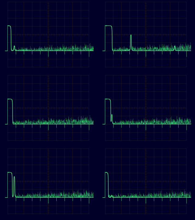
Figure 1: Display of range marks on screens with deflection modulation

Range marks
Range marks are markers for measuring distance that are displayed on a radar screen. They help the radar operator to quickly estimate the distance of an echo (target) from the radar site, similar to a scale on a map.
There are different methods of displaying them:
- On display units that use amplitude notation, they typically appear as pulses pointing downward. Some marks, like those in a 50 km grid, may be larger in amplitude. On older display units, they could also be engraved directly onto the glass surface of the cathode ray tube.
- On display units with brightness modulation, these range marks form lines or circles (so called range rings) at specific distances from the radar's site. These range marks don't always have to be “straight”: in fire-control radar, they can be “crooked” or even change dynamically, marking, for example, a destruction zone or an ideal launch time for defense missiles.

Figure 2: Display of range marks as concentric circles with low brightness on PPI-scopes with brightness modulation
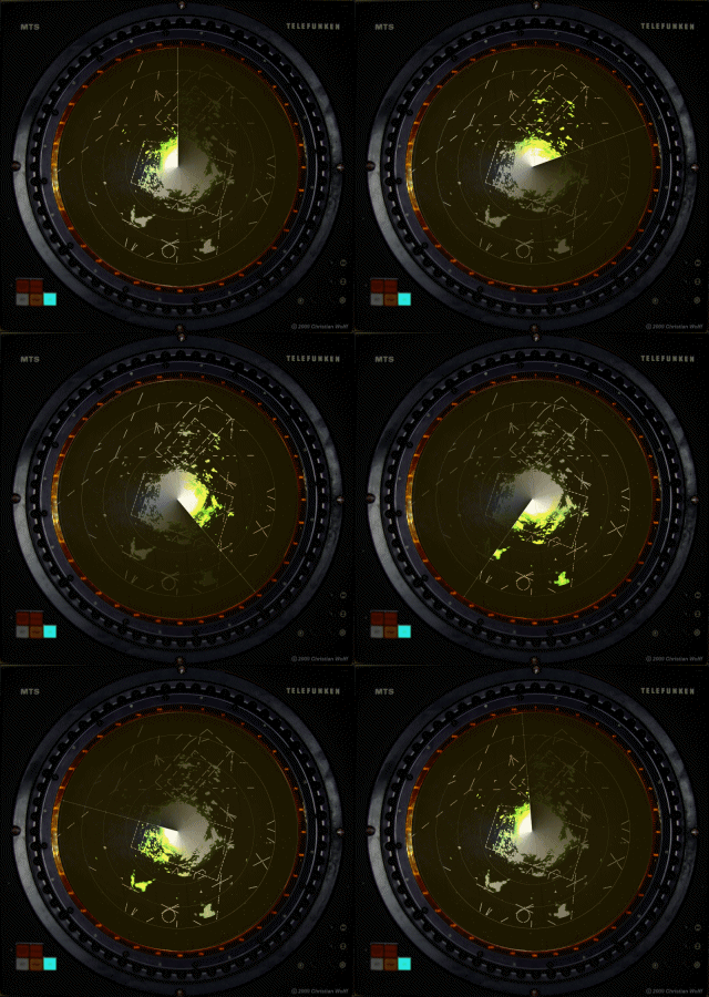

Figure 2: Display of range marks as concentric circles with low brightness on PPI-scopes with brightness modulation
On older analog radar sets, these range marks could be written on the screen very close to each other, for example, at intervals of 1, 2, 5, or 10 km. This was necessary to enable the operator to make the most accurate measurement possible, which he could then report via a telephone connection. With modern radar sets, this is no longer necessary: The measurement result is automatically transmitted electronically with maximum accuracy. Here, range marks are only displayed on the screens for overview purposes, usually at intervals of 50 or 100 nautical miles.
Due to the constant propagation speed of electromagnetic waves, these range marks are time marks with a constant distance between them. In older analog radar sets, they are generated by the radar’s time base, using a special synchronizer block. Here, these time marks can be generated either by frequency division from a central master oscillator or by a separate distance marker generator. The clock frequency is derived from the equation for distance measurement:


(1)
- c0 = speed of light = 3·108 m/s
- t = measured delay time [s]
- R = distance antenna - target [m]
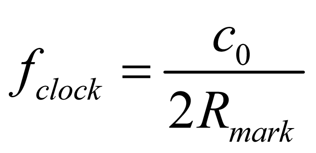
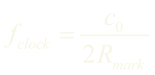
After replacing the delay time with the desired clock frequency f=1/t and subsequent conversion, we obtain:
(2)
For example, for the desired 10 km markers, this results in a clock frequency of 15 kHz. For range marks on a scale based on nautical miles, the conversion factor of 1 NM = 1,852 km must be taken into account, or the speed of light must be used as 162,000 nautical miles per second.