
Reflections at the Earth's surface

Figure 1: Fragmentation of the antenna pattern over reflective surfaces
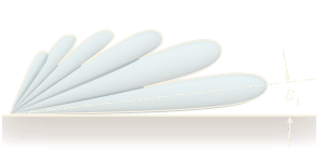
Reflections at the Earth's surface

Figure 2: Calculation aid for the resulting antenna pattern
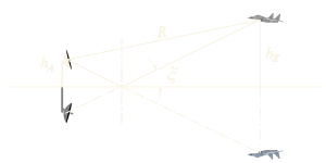
Reflections at the Earth's surface or other reflective surfaces occur when these surfaces are also illuminated by the radar transmitter due to insufficient antenna beamwidth. In this case, in addition to the direct signal path, there is a propagation path in which the electromagnetic waves are reflected off the surface — which is assumed to be flat — according to the laws of geometric optics. The reflected signal experiences a time delay due to the detour. If the direct and reflected signals have the same amplitudes but exhibit a time difference of half a wavelength due to the detour, interference can cause signal cancellation, which results in a significant fragmentation of the main lobe in the resulting effective antenna pattern.
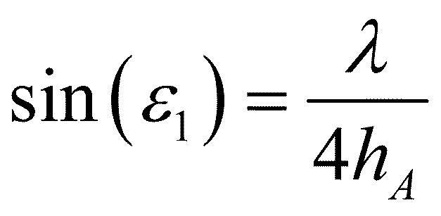
When calculating the resulting antenna pattern using a simulation program, the contribution of the signal reflected at the surface is obtained by supplementing the array with a second antenna positioned symmetrically with respect to the Earth’s surface. When the distance between the two antennas is large, a highly fragmented effective antenna pattern results, whose nulls indicate the directions for which this radar array is blind. For the elevation angle ε1 of the first main lobe, simple geometric considerations yield the angle from the following equation:
(1)

Figure 3: Reflection coefficient of seawater in the S-band as a function of the angle of incidence.

Figure 3: Reflection coefficient of seawater in the S-band as a function of the angle of incidence.
If low-flying objects over water are to be detected from a ship, the antenna must be mounted as high as possible to extend the radio horizon. At the same time, the wavelength should be as short as possible. For this reason, maritime navigation radars primarily operate in the X-band. However, the number of local minima decreases as the wavelength increases. In the VHF band, there would be only one significant minimum at approximately 10 to 11 degrees.
The depth of the local minima in the antenna pattern is determined by the reflection coefficient ρ of the Earth’s or water’s surface, which, according to Figure 3, depends on the frequency, the polarization, and the angle of incidence ξ. For the small angles of incidence relevant here, this reflection coefficient is always close to 1 at a phase angle of 180°, so that cancellation must be expected.