
Time sidelobe measurements
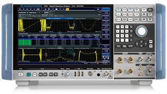
Figure 1: R&S®FSW signal and spectrum analyzer
(Courtesy of Rohde & Schwarz)

Time sidelobe measurements
Intrapulse modulation is often applied when a long detection range is required, and the radar transmitter uses solid-state technology. This method combines the advantages of good range resolution and high energy content of the transmitted pulse with relatively low peak power. An appropriate matched filter in the receiving channel of the radar compresses the radar echo signal in time. It increases the amplitude of the compressed pulse by the approximate pulse compression ratio. Pulse compression is a kind of autocorrelation function. In addition to the narrow main pulse with a high peak value in the time domain, it also generates time sidelobes at the output of the pulse compression filter.
The performance of pulse compression is influenced by the radar waveform, the quality of the circuitry, and the software, in the case of digital pulse compression. Therefore, a controllable, repeatable, and time-saving test environment is the key to achieving top-level radar performance. However, such measurements are less effective on radars already in use but allow radar system designers and engineers to efficiently optimize, verify, and test their modulation patterns, specific circuit components, and the entire system to improve radar performance.
For these measurements can be used the R&S®FSW signal and spectrum analyzer (Figure 1). It enables measurement and analysis of time sidelobes to optimize compressed radar signals as well as to optimize radar hardware components and systems. In addition, signal interference, such as intentional echo signal distortion, can be easily verified. For the test setup, the radar transmitter is connected to the RF input of the R&S®FSW via suitable attenuators (maximum power: 30 dBm). An ideal waveform in digital I/Q format is loaded into the analyzer, which operates as a pulse compression filter. The ideal waveform can be synthetically generated or previously recorded with the R&S®FSW and made available on a USB stick as a reference.
The actual measured shape of the transmit pulse is cross-correlated with the ideal I&Q waveform stored as a reference. If the measured pulse were ideal, the two waveforms would be identical and show the same narrow main curve. In practice, however, the waveforms differ, for example, due to inaccuracies in modulation, phase noise, and reflections from mismatches between processing stages. The more the waveforms differ, the less effective the compression ratio. As a result, the side lobes become larger, which affects the performance of the whole radar system. They may mask smaller echo signals or cause false alarms.
Developers of radar systems can improve their radar design by automated and reproducible measurements and check them immediately.