
Noise Figure
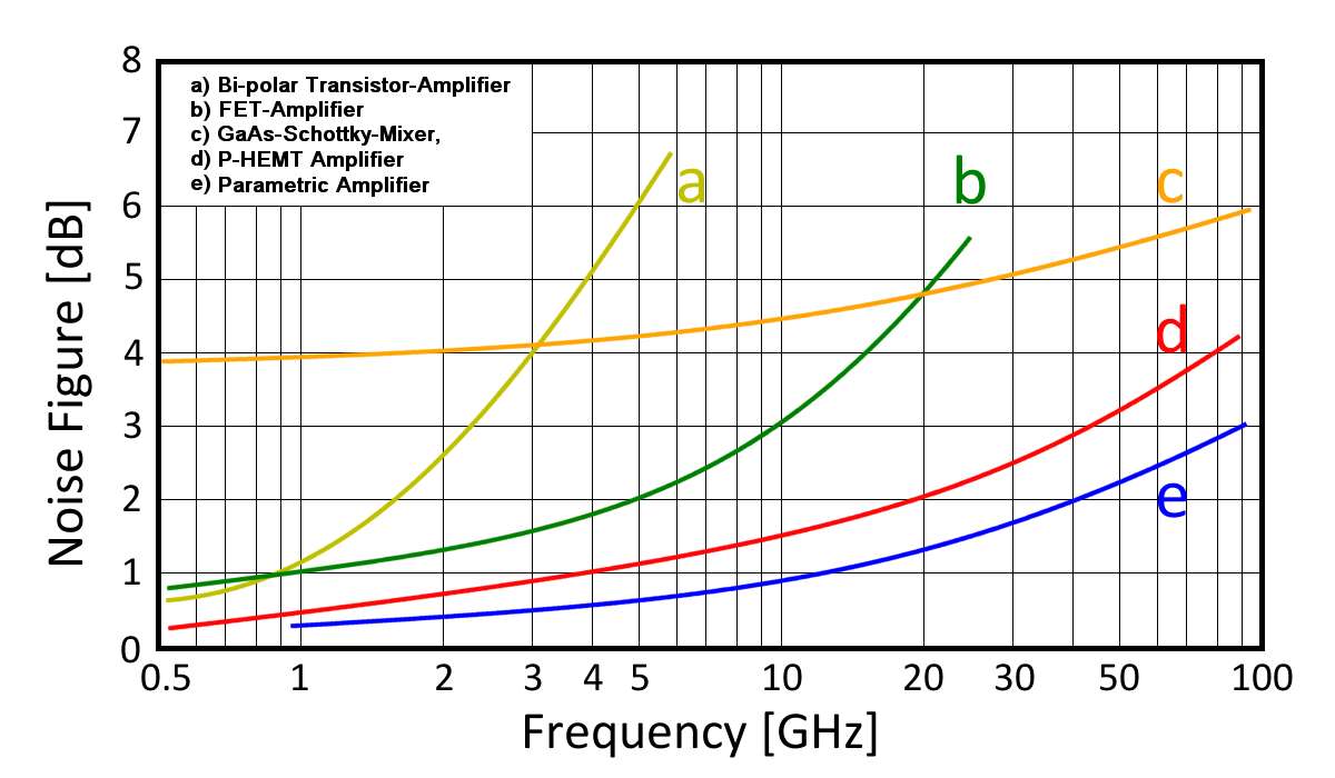
Figure 1: Exemplary noise figures of different receiver input stages
Figure 1: Exemplary noise figures of different receiver input stages
Noise Figure
The noise figure (NF) and noise factor (F) are a measure of the inherent noise in a linear module such as an amplifier stage or a radar receiver. They represent the ratio of the signal-to-noise ratios at the input and output of the module. The terms “noise figure” and “noise factor” refer to the same physical quantity, with the noise factor being a linear value and the noise figure being the decibel representation of the noise factor. The noise must always be specified with the frequency for which it was measured. In the case of high-frequency radar assemblies, the current carrier frequency is typically assumed.
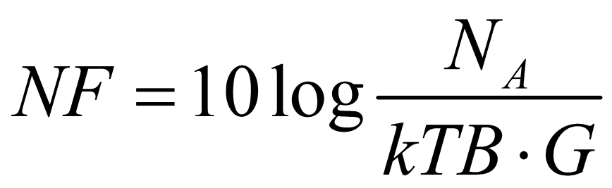
If the output noise power of the receiver is NA and the total gain G is given, then the noise figure of this receiver results from
(1)
- NA = output noise power of the receiver
- G = total gain
- k = the Boltzmann constant
(1,38·10-23 Joules/K) - B = the bandwidth in Hertz and
- T = the effective temperature in Kelvin
In this equation, kTB represents the thermal noise at the input of the module, which is then amplified by the module. As a result, the output noise needs to be divided by the respective gain factor to effectively compare it with the input noise.
In modern radar sets, the noise figure is automatically measured by the BITE (Built-In Test Equipment) by inputting a defined power test pulse at the receiver’s input with the antenna switched off. The size of this test pulse at the output is used to determine the current gain factor. The quantity kTB is typically a fixed tabular value for a temperature of 68°F (20°C or 293 K). The average noise at the output is then the second value for determining the noise figure.
With older radar sets, this process had to be carried out manually by the technician.