
Pulse-Pair Processing
Pulse-Pair Processing is a method of suppressing echo signals from stationary targets. Only the echo signals from moving targets are displayed on the screens. Hence, the term “moving target indication,” commonly abbreviated to MTI.
To distinguish between a moving target and a fixed object with the help of the Doppler frequency, at least two periods of deflection must be compared with each other. Since the Doppler frequency (a few Hertz) is small compared to the transmitted frequency (many Mega-Hertz), a phase comparison is technically better to carry out than a direct frequency comparison. The storage of a deflection is carried out in suitable memory media, in the past in special analogous vacuum memory tubes, later also with a chain of condensers (distance: digital, signal: analogous), and today only in digital memory cells.

Stage
Stage
signals
transmitted
power
Figure 1: functional block circuit diagram of a coherent-on-receive receiver

Stage
Stage
signals
transmitted
power
Figure 1: functional block circuit diagram of a coherent-on-receive receiver
Stage
Stage
signals
transmitted
power
Figure 1: functional block circuit diagram of a coherent-on-receive receiver (interactive picture)

Figure 2: The phase shifting of the received signal

Well, a fixed target suppression happens by the phase comparison of the echoes received by several pulse periods (pulse-pair processing).
If the phase relationship is always equal, then there is no phase difference, and the target will be suppressed.
If the target has moved, the phase difference is unequal to zero, and the target will be shown on the screen.
To get the necessary frequency reference for the phase detector, a high-precision
coherent oscillator
(called “Coho”) is synchronized with the down-converted on the IF frequency transmitting pulse.

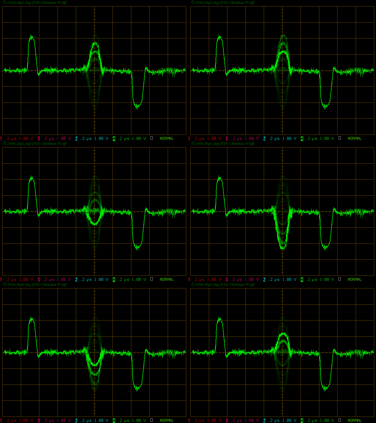
Figure 3: Oscillogram of an output signal of a phase-detector
The echo signal of a moving target at the output of the phase detector changes its value and also its polarity in every pulse period. A fixed clutter signal will keep its value and polarity in every pulse period.
A pulse period is stored in a memory. This memory stage has a memory cell for each range cell and delays the whole scan for one pulse period (PRT). Both periods, the actual period and its predecessor, lead to an extractor. The output of this stage is the difference between the input signals. Clutter with a constant amplitude will be eliminated. Moving targets pass this stage. In this way, the moving target produces an output signal, and the fixed clutter doesn’t do this. (see the tooltip on test point TP2 in Figure 1!)
Description of the modules in the block diagram

Figure 3: Echo signals of fixed clutter have the same amplitude pulse to pulse and can be cancelled:
magenta: output of the phase-detector (aktually period)
green: output of the memory (delayed period)
blue: cancelled video