
2D or 3D Radar

Figure 1: Diagram of a typical 2D Radar, the rotating cosecant squared or fan beam antenna pattern.
2D or 3D Radar
2D Radar
An air surveillance radar covers within an area of a certain size around the radar, and must listen for echo signals. Its antenna pattern is adjusted for the specific task. Mostly the antenna forms a rotating fan beam or cosecant squared antenna pattern. This form of volume scan is then called 2D radar. Such radar can measure only two coordinates to determine the position of aims. It can detect two superimposed flying airplanes only as a single (but then larger) target.
For the third coordinate, the height information (either an elevation angle or as calculated from altitude), had to work 2 radars in combination at the beginning of radar technology (about the 2nd World War and in the post-war period). One of the radar was working as surveillance radar and the second radar device was then specialized as a so-called height-finder. Both types, the search radar, and the height-finder can measure only two coordinates. In both cases, it is 2D radar equipment.
In used by the military radars the cost factor plays a subordinate role. However, radars in air traffic control must not be too expensive. Therefore, only 2D radars are used for air surveillance here mostly. The altitude information is then provided by the secondary radar.
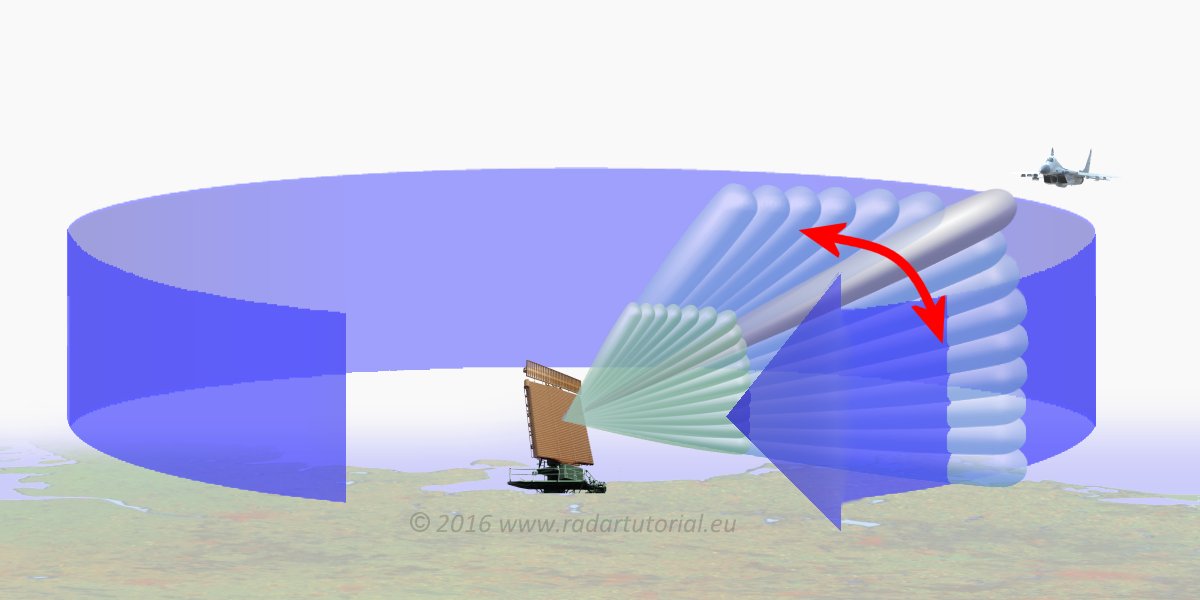
Figure 2: Diagram of a typical 3D Radar, a mix of vertical electronic beam steering and mechanically horizontal movement of a pencil beam.

Figure 2: Diagram of a typical 3D Radar, a mix of vertical electronic beam steering and mechanically horizontal movement of a pencil beam.
3D Radar
If the measurements of all three space coordinates are made within radar system, this one is called as 3D Radar.
A special form of 3D radars is the weather radar using a very narrow pencil beam. After each scanning rotation, the antenna elevation is changed for the next sounding. This scenario will be repeated on many angles to scan all the volume of air around the radar within the maximum range. For a complete cycle with rotation and tilt of the antenna in all directions but it takes up to 15 minutes. This time approach is not suitable for an air surveillance radar because very fast aircraft can travel a huge distance in a very short time. An airplane with supersonic velocity travels nearly 300 km during this interval!
In 3D radars for air surveillance, a significant technical effort was initially required. The 3D radar needed to have multiple receive channels operating in parallel, and the radar antenna had to deploy various antenna patterns during the receiving time. An example of such radar is the Medium Power Radar (MPR), which is no longer in service today. Its enormous parabolic antenna features 36 feed horns and configures a total of 12 different narrow antenna beams that are aligned one above another, each at different elevation angles. As a result, the echo signals are processed based on which channels of the receive channels are activated and the direction indicated by its beam. The radar processor interpolates an accurate elevation angle of the received echo signal from this information. The target’s height is calculated using this elevation angle and the measured distance. An extremely high pulse power had to be transmitted simultaneously in all 12 directions during the transmission phase. Consequently, both transmitter power amplifiers are designed to utilize pulsed high-power klystrons to generate pulse power of up to 20 megawatts.
Older 3D radar devices with a planar or linear phased array do not transmit simultaneously in all observed directions. Instead, this occurs sequentially over time. These antennas can only scan within a limited swivel angle. There are two possibilities: either the antenna rotates in azimuth while electronically scanning the elevation angle, or four planar antennas are statically distributed around a carrier, each covering only a quarter section of the hemisphere. Both variations allow for overall coverage around the radar site. In this setup, the radar transmits in a specific direction and then waits for the echo signal from that direction.
The rotating antenna has a significant disadvantage. Since each elevation angle is scanned sequentially, the antenna cannot rotate too quickly to avoid gaps in reconnaissance within the limited time budget. In contrast, the version using static antennas benefits from time scheduling, allowing four radars to scan the space simultaneously. These four radar front-ends are part of a common radar data processing and display system. Consequently, the radar system can operate more flexibly and serve as a multifunction radar. Thus, modern radars are always multifunctional.
Since the use of the advantages of digital beamforming and the possible parallel digital processing of all receiving channels, this timing problem is completely overcome. However, the entire scanned area must then be illuminated with the pulse power during the transmission time, as like in MPR at that time. With a single, very specific “Crow’s-Nest Antenna”, patented by the Fraunhofer Institute for High-Frequency Physics and Radar Techniques (FHR), the entire hemisphere around the radar site could be controlled simultaneously.
4D Radar?
Time is sometimes defined as the fourth dimension. Applied to the target coordinates of radar (azimuth, elevation angle and slant range) this would be the Doppler frequency. However, the Doppler frequency is also measured by classic 2D radars without them mutating into a 3D radar. Because a 3D radar measures Doppler frequencies as a fourth measurand (and any modern reconnaissance radar should be able to do that) should it suddenly be a 4D radar?
So 4D radar is just a sales-promoting buzzword that has nothing to do with the fourth dimension in physics. It simply refers to the radar's capability for what is known as Micro Doppler Processing — that is, the detection of moving parts on an object that is otherwise stationary or moving at a different speed, most commonly a Jet Engine Modulation.