
AN/SPS-17
Description of the radar set, tactical-technical characteristics
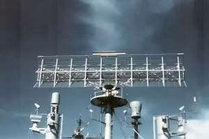
Figure 1: AN/SPS-17A

 Hersteller:
General Electric
| Specifications | ||
|---|---|---|
| AN/SPS-17 | AN/SPS-17A | |
| frequency: | 215 … 225
(VHF band) |
415 … 420 MHz
(UHF band) |
| pulse repetition time (PRT): | ||
| pulse repetition frequency (PRF): | 300 Hz | |
| pulsewidth (τ): | 5 µs | |
| receiving time: | ||
| dead time: | ||
| peak power: | 1.5 MW | |
| average power: | 2.25 kW | |
| instrumented range: | 200 NM (≙ 370 km) | |
| range resolution: | ||
| accuracy: | ||
| beamwidth: | 18° | 9° |
| hits per scan: | ||
| antenna rotation: | ||
| MTBCF: | ||
| MTTR: | ||
AN/SPS-17
The AN/SPS-17 in its original version was a long-range air surveillance radar that operated in the VHF band (IEEE designation) or in the B band (NATO designation). It used a so-called “mattress antenna” with four rows of seven dipoles each in front of a common grid reflector measuring 8½ × 17½ feet (≙ 2.6 × 5.34 m). This antenna had a gain of 18.2 dBi and a vertical beamwidth of 30°. However, only two prototype units of this variant were built in fiscal year 1955.
AN/SPS-17A
Starting in 1957, a different antenna measuring 4 × 17.5 feet (≙ 1.3 × 5.34 m) with two rows of dipoles, each with an angled grid reflector, was put into service. It provided more than double the antenna gain of 22 dBi with only half the aperture angles, which was primarily due to the significantly higher resonance frequency. Twenty-two units of this version were deployed.
An experimental radar based on the 220 MHz version was also built for use in an airship gondola. This version featured the “mattress antenna” at only half the height of the original, as well as a transmitter with a pulse power of just 500 kW.
Sources:
- Evolution of Naval Radio-Electronics and Contributions of the Naval Research Laboratory, NRL-Report 8300, ADA084225.pdf, p. 190
- Louis A. Gebhard, “An Experimental 220-mc Radar Systen for Airships”, NRL-Report 4958, p. 32