SLA 3
Description of the radar set, tactical-technical characteristics

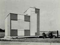
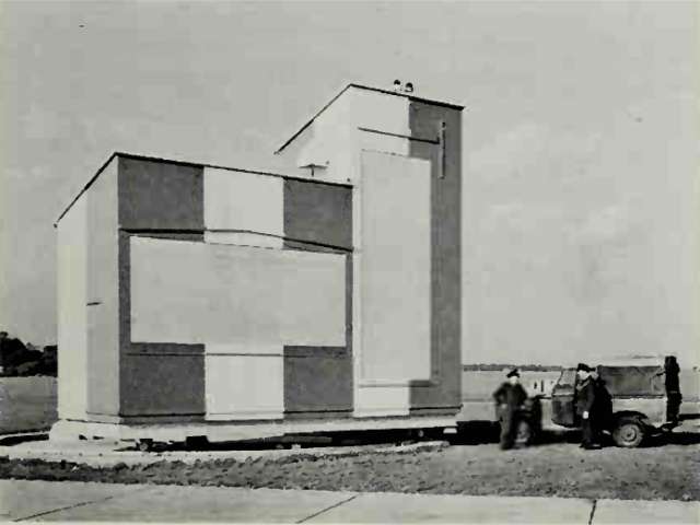
Figure 1: SLA 3/B1 at Bedford Regional Airport (UK)

| Specifications | |
|---|---|
| frequency: | X band |
| pulse repetition time (PRT): | |
| pulse repetition frequency (PRF): | |
| pulsewidth (τ): | |
| receiving time: | |
| dead time: | |
| peak power: | |
| average power: | |
| instrumented range: | 15 NM (≙ 28 km) |
| range resolution: | |
| accuracy: | |
| beamwidth: | |
| hits per scan: | |
| antenna rotation: | |
| MTBCF: | |
| MTTR: | |
SLA 3
SLA 3 (sometimes also SLA.3) was operating in X band unattended and remotely controlled precision approach radar.
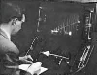
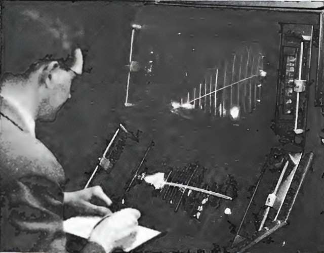
The radar uses frequency scanning phased arrays. The glide path and the course were shown on two displays using 17-inch cathode ray tubes. The display group could be installed in the control center up to 1½ miles (≙ 2 700 m) away from the radar head.
This kind of radars were used since 1966 at several airports e.g. at the Bromma Airport in Stockholm and the Kai Tak Airport in Hong Kong.
The SLA.3-B was a modernization in which polarization plates could be installed in the antenna waveguides to transmit with circular polarization. With SLA.3-B, this was still done manually and required a longer shutdown time for the transmitter. With SLA.3-C, these were inserted into the waveguides by a motor.