Bends and twists in a waveguide
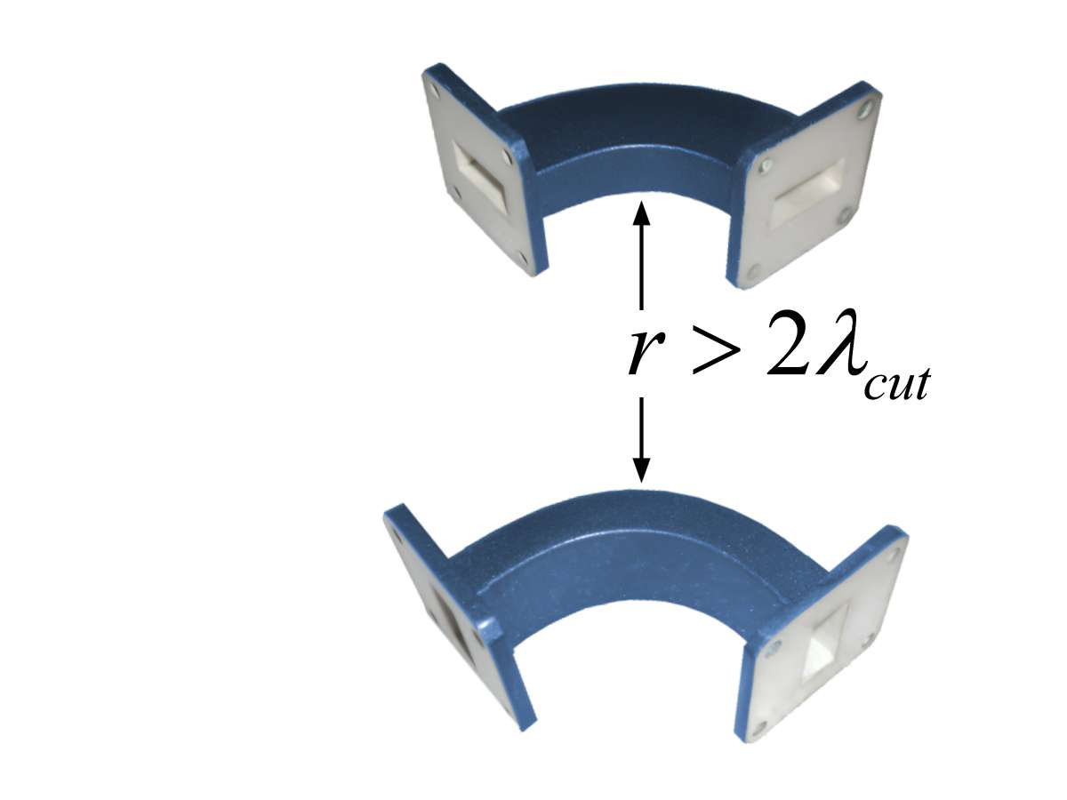
Figure 1: H-bend and E-bend
Bends and twists in a waveguide
Bends and twists in waveguides must be designed so that reflections caused by sudden changes in the cross-sectional shape are avoided. A prerequisite for low-reflection propagation of energy in a waveguide is that its size and shape remain constant over its entire length. Any sudden change in size and shape causes a change in impedance and thus reflections. If such reflections are undesirable, any change in size and shape must be made gradually, or special devices must be used that are designed in accordance with certain rules.
Bends
The bend radius is critical and should be gradual and greater than two wavelengths. In this case, reflections are kept to a minimum, regardless of whether the bend is made on the wide side (E-bend) or the narrow side (H-bend) of the waveguide.
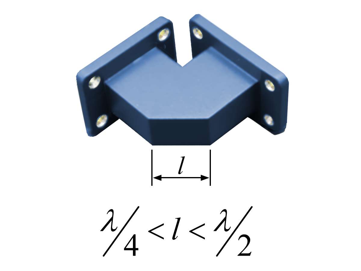
Figure 2: Miter bend
Miter Bends
Special miter bends are used for sharp curves, e.g., 90°, that cannot comply with these radii. Very sharp bends usually result in reflections. These are avoided by using specially adapted angle pieces, which direct the reflections in the correct direction via a surface with an angle of 45°.
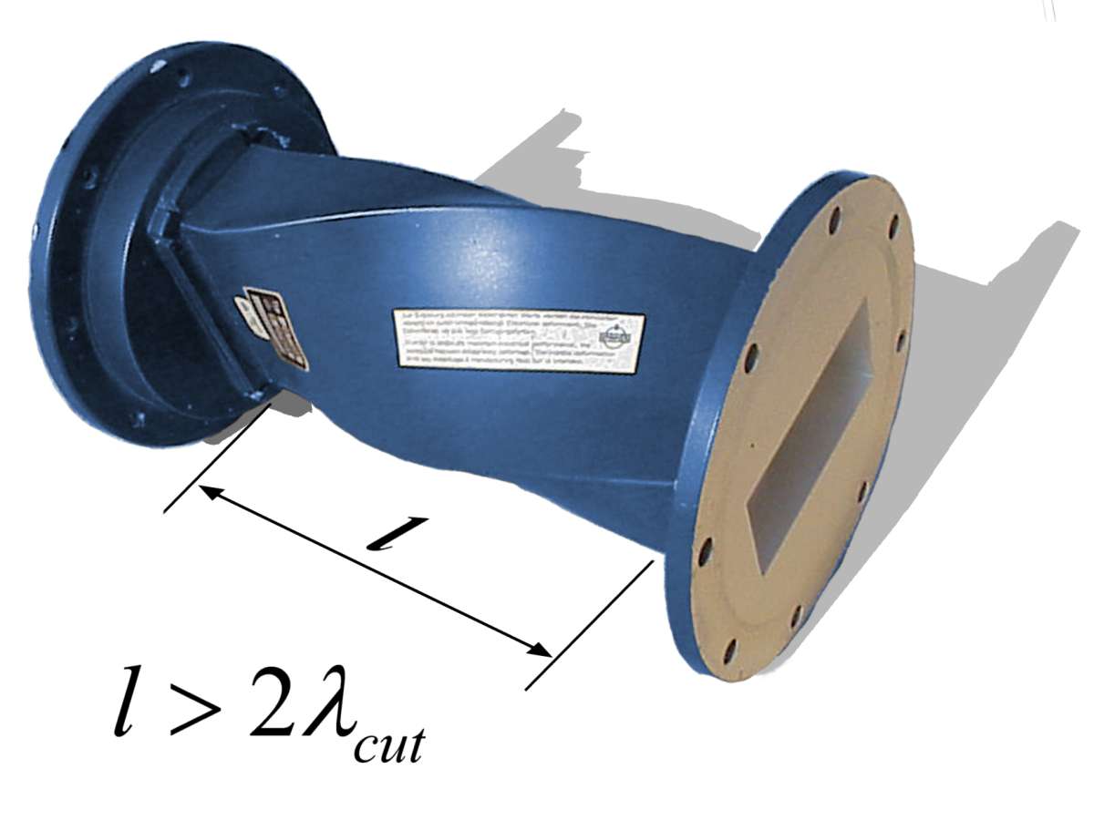
Figure 3: Waveguide Twist
Twists
Torsion (twisting) of the waveguide around its longitudinal axis (e.g., to rotate the polarization plane) must also be gradual and should extend over at least two wavelengths.
Flexible waveguides
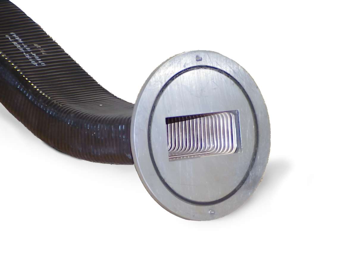
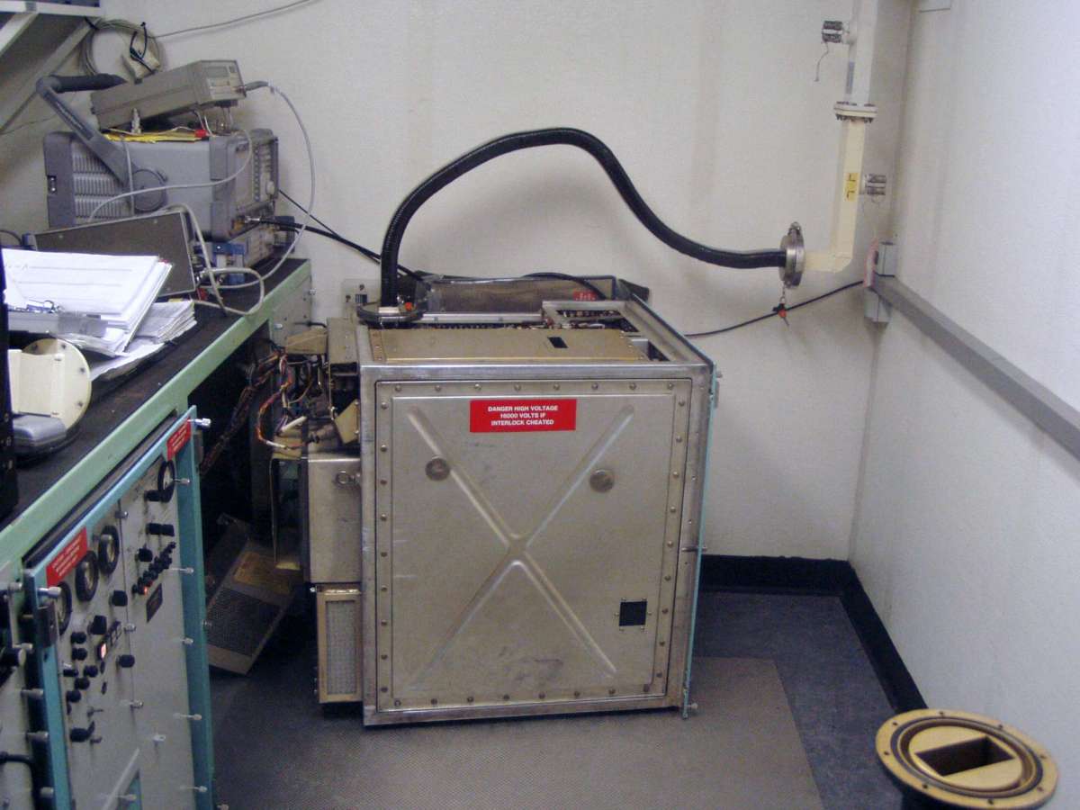
Flexible waveguide sections are often installed to allow for any type of curvature or rotation. Their flexible part can be bent in any direction. However, the attenuation in such waveguides is higher than in fixed sections. Such waveguide sections are therefore usually kept very short. They are used, for example, in radar antennas whose angle of attack can be changed, as well as in maintenance work, e.g., when transmitter blocks are pulled out to take measurements and make adjustments.