
Power matching and impedance
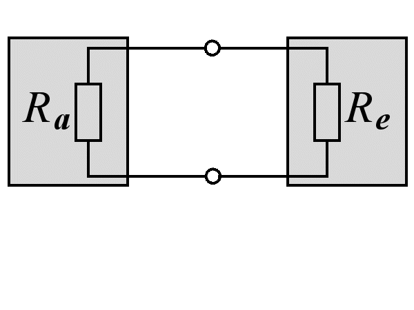
Figure 1: Impedance matching of two subsystems
Power matching and impedance
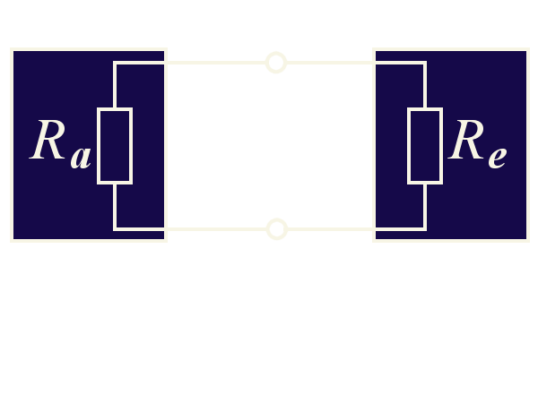
To achieve the maximum power output from a device, it is important to match the power of each module junction internally. This requires ensuring that the output resistance of the first module (Ra) is equal to the input resistance of the second module (Re). If the resistance values are not matched, some of the power will be reflected due to the mismatch, leading to reduced efficiency.
The characteristic impedance or line resistance can be calculated using extensive line equations, resulting in a clear equation:


(1)
- ZL: characteristic impedance in [Ω]
- L’: Inductance in [mH/km]
- C’: Capacitance in [nF/km]
The above formula applies to the simplified case of a lossless line, with the conditions
R’ = 0 Ω/m and
G’ = 0 S/m.
It is observable that the characteristic impedance remains constant regardless of the frequency under this situation.
If the length of the cable is shortened in both the denominator and numerator,
the capacitance and inductance can be included in the formula mentioned above instead of the cable coatings.
This adjustment is necessary for both high and low-frequency assemblies such as loudspeakers, but impedance of the cable has no effect on low-frequency assemblies because the cable is much shorter than the wavelength.
Frequency independence of the impedance
Could you please clarify why the value of a capacitor C or an inductor L needs to be frequency-dependent? As far as I understand, only the reactance XC of the capacitor or the reactance XL of the inductance are frequency-dependent. However, I am not asking about these quantities.
To help explain the relationships, we can modify the units of measurement slightly. We can utilize the table provided in DIN 1301-2 for this purpose. As we are only concerned with the principle at hand, we can leave out the unit prefixes „milli“ and „nano”.


So here at the latest:
You can see that the impedance of a transmission line must be frequency-independent,
as its unit of measurement is the frequency-independent „ohm“.