Power meters

Figure 1: R&S®NRX. power meter equipped with two measuring sensors.

Figure 1: R&S®NRX. power meter equipped with two
multipath diode probes.
(Courtesy of
Rohde &Schwarz)
Power meters
The rapid development of microelectronics has also changed measurement equipment. In principle, the complete measurement sequence for an RF power measurement takes place inside the small sensor (Fig. 3). Only the data of the measurement are still transported somewhere and so any computer or laptop with a suitable interface and the appropriate software can be used as a display device. However, there are also special basic devices that practically contain a computer and can display the measurement result (Fig. 1). Where two measuring devices were used in the past, two or more measuring heads can now be connected to one basic device.
Earlier power meters could only display an average value. When measuring RF pulses, a pulse power had to be calculated from the measured average power using a duty cycle that was assumed to be known. With the new measuring instruments, the course of the measured RF signal is displayed as on an oscilloscope and a measuring range can be defined directly above the pulse to be measured so that a pulse power can also be displayed directly.
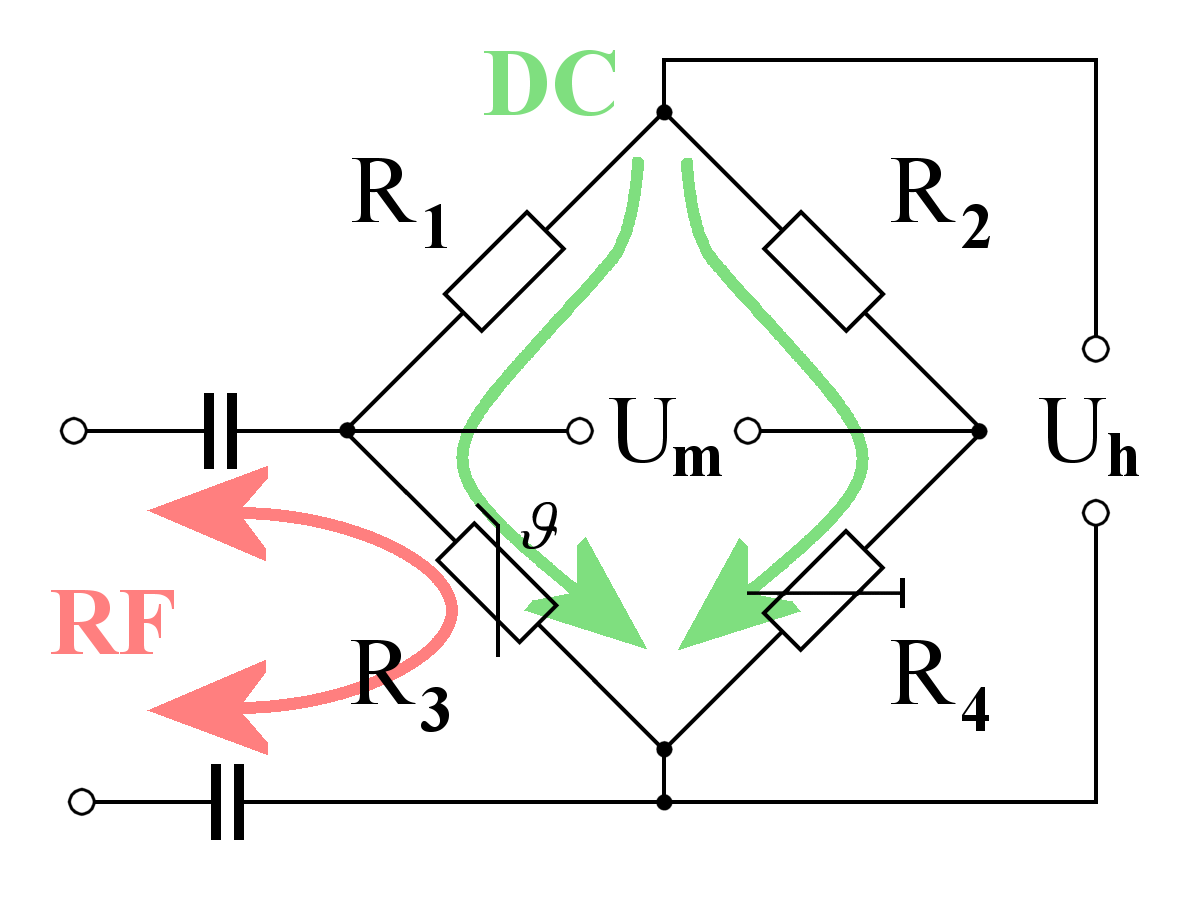
Figure 2: Measuring bridge for the thermal method

Power sensor
The power sensor contains a Wheatstone bridge with a thermistor (Fig. 2). This measuring bridge consists of two voltage dividers R1 with R3 and R2 with R4 and is supplied with an auxiliary voltage Uh. If the ratio of the resistances in each of the voltage dividers is the same, then the measurement voltage Um is zero. However, the thermistor R3 changes its resistance value depending on the temperature. A zero adjustment could then be made with the potentiometer R4 if the room temperature deviates.
Via this thermistor flows once the DC component from the wiring of the resistance measuring bridge, but additionally via the capacitors also the high-frequency component from the measuring connection. This additional power heats the thermistor and increases its internal resistance. This causes the measuring bridge to become unbalanced, and measurable equalizing currents flow, from which the magnitude of the RF power can be calculated.

Figure 3: Power sensors using the thermal method
(Courtesy of Rohde & Schwarz)

The classic version of a power sensor has a very high measurement accuracy. Because of this method of operation, these thermal power sensors are very sluggish. On the other hand, they do not care at all about the frequency of this RF power. Therefore, they are extremely broadband and their bandwidth is limited only by the capacitances created by matching the impedance of the supply line. They are also completely independent of waveform or any modulation.
Another advantage is that the thermistor also does not care whether additional RF power or an additional DC current flows through it. Therefore such a power sensor can be calibrated internally with DC current!
Handling
A power sensor for RF measurement is very sensitive to too high a load. A too high RF power would destroy the thermistor and make the device unusable. Therefore it should always be estimated before the measurement, which measuring result is expected at the measuring point at all and whether it is compatible with the sensor. In case of doubt, the sensor should be protected by upstream attenuators, which can then be removed step by step depending on the measurement result, if the measurement result has a value that is much too small.
Source: