Radar Echo Generator

Figure 1: Example of a HF signal generator
(Courtesy of Rohde & Schwarz)

Radar Echo Generator
For many measurement and testing tasks on a radar set, an artificially generated echo signal is required, which has a precisely definable size. Such tasks are for example:
- Receiver checks
- Testing the moving target detection
Depending on the modulation of the transmission pulse, there are two different ways to generate such an echo signal for inspection or measurement. Classical pulse radars are still quite simple: here only the trigger pulse has to be delayed to the desired distance and the signal generator generates the desired high-frequency signal. (Such a trigger pulse is always available in every radar set for synchronization of measuring instruments).
It becomes more difficult if the radar uses an intra-pulse modulated transmitter pulse whose waveform is unknown to the signal generator.
Some radars, especially in air traffic control, alternately use both methods: a very short internally unmodulated pulse for short distances and usually a linear frequency modulated longer transmission pulse for long distances. If both types of echo signals are processed in the same receiving channel, it is often sufficient to use only the simpler variant.
Intrapulse modulated signals
With intra-pulse modulated signals, the measuring instruments have to meet higher requirements. In the first step, the current transmitted signal must be received and analyzed. For this purpose, the transmitted signal is demodulated synchronously, and the digitized I&Q data will be transmitted to the second measuring device via a data cable. The second measuring device is a so-called vector signal generator and modulates its high frequency exactly with these I&Q data. This results in a 1:1 copy of the transmitted signal but with a slight delay due to the propagation times in the measurement units. This copy can be additionally modified by time delay (range), Doppler frequency shift (radial velocity), and attenuation (by Radar Cross Section).
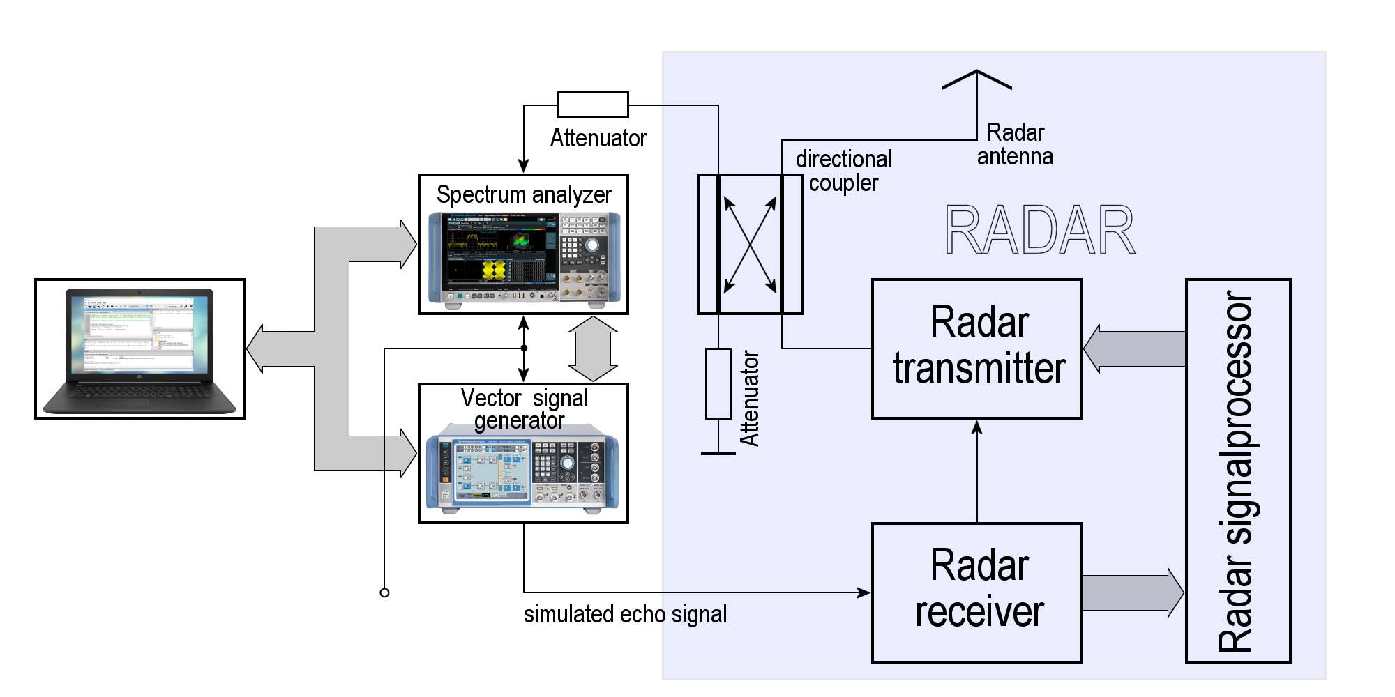
Figure 2: Measurement setup for a synthetic radar echo with an intrapulse modulated radar

analyzer
Signal
Generator
transmitter
receiver
coupler
Figure 2: Measurement setup for a synthetic radar echo with an intrapulse modulated radar (interactive picture)
This measurement setup shown in figure 2 must be modified depending on the availability of measuring instrument connections.
In most cases, radars with a passive antenna have a directional coupler built into the feed line to the antenna. This serves to measure the power of the transmitter and the standing wave ratio of the feeding line to the antenna. It can also be used to feed in the echo signal if the connection of the terminating resistor is reversed. But what is not possible is: to take a sample for the analysis of the transmitted signal and feed the simulated echo signal at the same time! For this purpose, instead of the directional coupler, a test socket would simply have to be installed parallel to the antenna feed line, which would then be mismatched and would worsen the impedance of the antenna feed line. For this reason, only a part of transmitting power can be taken from this socket. Another connection must be found for feeding in the simulated echo signal. The easiest way is to disconnect the cable directly at the receiver input and connect the measuring cable with the test signal.
However, this setup is not possible with active phased array antennas. There are no test sockets on the radar which could be used for this purpose. In the test setup shown in figure 2, everything that belongs to the radar and is highlighted in blue can now be omitted. Instead, small antennas adapted to the transmission frequency are connected to both cables. Now the spectrum analyzer receives the transmitted signal (usually from the side lobes of the antenna). The signal generator transmits the echo signal in the close range of the radar antenna. Both measuring instruments must, therefore, be installed outdoors at a certain distance from the radar antenna. The remote control via LAN cable allows operation from the radar shelter.
Repeater-Jammer
This measurement set-up outside the radar shelter works with every radar unit. But it is also in principle the circuit of a jammer, which can produce a strong false target on the users' radar displays. In the case of air traffic control radars, such a measurement set-up should be registered with the air traffic controllers, in the case of air traffic surveillance radars with the radar controllers.
Coherence?
Is this measuring arrangement according to Fig. 2 capable of simulating
coherent echo signals?
This question is not so easy to answer with yes or no. It depends on:
First of all, it depends on whether the generation of the simulated echo signal in the measurement setup happens fast enough. Since the phase of the transmit signal is also evaluated and taken into account when generating the echo signal the generated echo signal is coherent to this one transmitted pulse. So if the echo signal is still available in the same pulse period, one can safely assume coherence.
Second, it depends on whether the radar transmitter is fully coherent i.e. whether the radar’s transmit pulses are coherent with each other. If not (which is always the case for transmitters using a magnetron), then this circuit can only be coherent within one pulse period. For this case, one speaks then of coherence on the receiving path. Since this is then also true for the next following transmitting pulse, this measurement setup can generate an echo signal with the properties of a fixed target. Targets afflicted with a Doppler frequency can also be simulated while an additional phase change can be modulated onto the simulated echo signal.
However, if the radar transmitter is of fully coherent type, then its transmitted pulses are also coherent with each other. In this case, the coherence of this measurement setup is independent of whether the simulated echo signal is still available in the same pulse period or not. Thus the echo signal would be coherent also if it would be available only several pulse periods later.
Sources and additional information: