Generator using Coaxial Resonant Stubs

Figure 1: Cutaway view of a generator for VHF Radar using Coaxial Resonant Stubs

Figure 1: Cutaway view of a generator for VHF Radar using Coaxial Resonant Stubs
Figure 1: Cutaway view of a generator for VHF Radar using Coaxial Resonant Stubs
Generator using Coaxial Resonant Stubs
An RF generator uses resonant circuits to generate oscillations on a given frequency. At higher frequencies a coaxial line of length λ/2 can be used as a resonant circuit also. Often the diameter of this coaxial line is so big that the planar triode wired as an amplifier can be mounted into this coaxial line stub geometry. With help of shorting plungers, the resonant frequency of the line stubs can be changed.

Figure 2: Cutaway model of a planar triode

connection
connection
connection
Figure 2: Cutaway model of a planar triode
In the calculation of the resonant frequency of the grid circuit, the parasitic capacitance of the planar tube Cgk between grid and cathode is included. The coaxial stub must have inductive characteristic therefore, i.e. it must be a little bit longer than the half wavelength. For positive feedback are slots in the tubing between the grid and the anode circuit. The produced RF-power is fed through a coupling pin with a sliding contact from the grid circuit into a coaxial cable. This kind of RF-generator can be used for a frequency range from 150 MHz up to the lower L-band. In older radars, these generators have been used as a self-oscillating high-power transmitter. The pulse power (Pout) e.g. of the VHF-radar P-12 “Spoon Rest” was of 160 ... 250 kW (dependent on the frequency; equivalent to about 540 watts average power).
Planar Triode
A planar triode is a vacuum tube, in which the electrodes (cathode, anode and control grid) are not as usually arranged cylindrical into one another but are arranged disk shaped one upon the other with a small distance of each other. In a triode there are always parasitic anode-to-grid capacitances caused by constructive reasons. These capacitances make it difficult to use the tube at higher frequencies, and can be kept relatively low in the planar triode. The physical construction makes it easier to use the tube in circular cavity resonators.
Characteristic for a planar triode is often a conical structure and a large heat sink at the cathode (and often at the anode too). The very massive contact areas of the connectors of the electrodes are made of copper or brass, and are silver- or even gold-plated at smaller tubes mostly.
The cathode filament is a so-called direct heating, i.e. one end of the carbonized Tungsten-filament has direct contact with the cathode. Using a higher filament voltage the output power of the planar triode can be increased. In this case the filament voltage must be increased slowly to avoid damaging the cold filament wire.
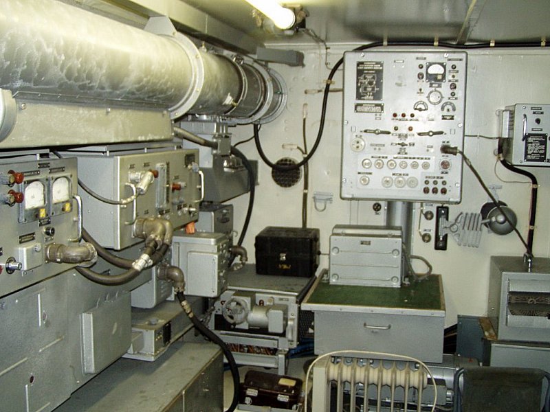
Picture gallery of Generator using Coaxial Resonant Stubs

Figure 3: Planar triode GI 19 B, used as selfoscillating transmitter in Russian radars P-12 “Spoon Rest B” and P-18 “Spoon Rest D”


