Noise
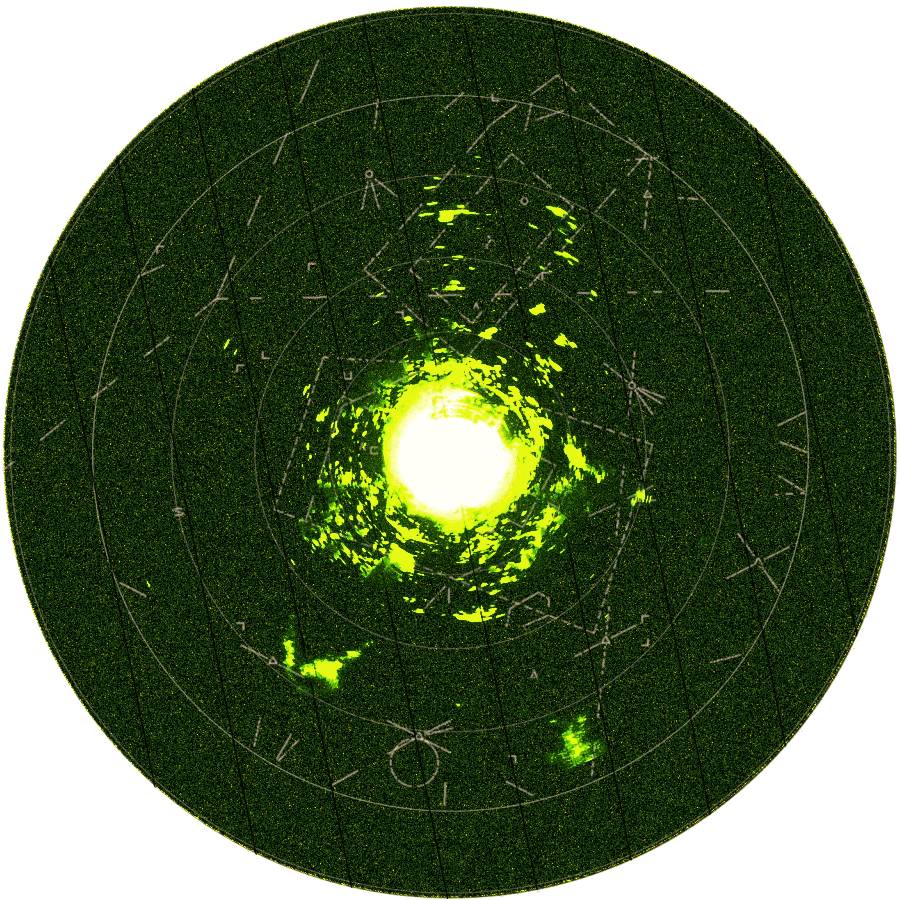
Figure 1: Background noise at a PPI-scope

Noise is a random, usually unwanted, signal in a lot of applications:
- you can hear it in acoustic signals as an additional constant fizzle,
- you can see it as variation in brightness or color information in a picture or a video sequence,
or (see in enlarged figure 1) as pointwise variation in brightness at the whole display of the PPI-scope of radar, and - you can measure the noise voltage (or noise floor) on an oscilloscope
or can see it as „green grass” at an A-scope in a Radar system.
Noise is most apparent in regions with low signal level, such as the weak received echo-signal in radar receiver. Noise is characterized by its statistical properties. Noise that contains all frequencies with equal amplitudes is called „white” noise. The „white” noise contains equal power within a fixed bandwidth at any center frequency. „White noise” draws its name from white light in which the power spectral density of the light is distributed over the visible band. An other type of electronic noise is frequency dependent, with a 1/ƒ, or so-called „pink” spectrum. Noise occurs in almost all electronic devices, and results from a variety of effects.
The sources of noise arise from inside and outside a circuit. Along with the signal power, a noise power (interference power) is received by the radar antenna. The received noise depends on the frequency ƒ and the receivers band width B. Antenna equivalent noise temperature is often quoted noting that it is elevation angle dependent. This interference power comes from extraterrestrial radiation sources (galactic or cosmic noise), mainly in the Milky Way, absorption of electromagnetic radiation in the atmosphere, and the noise temperature of the Earth. Since this noise can't be seperate from the backscattered radar signals, the received noise will be amplified like the radar signals in all stages of the radar receiver, too.
Noise sources within the circuit produce an internal noise power, whose most frequent causes are semiconductor noise and thermal noise of ohmic resistances or conductance and the noise current of charge carrier currents. The thermal noise is based on the irregular movement of the charge carriers in the resistance material, contributing to the current flow. The temporal average value of this current is not zero, the square temporal average value against it.

Figure 2: Noise at an open measuring cable of an oscilloscope

Figure 2: Noise at an open measuring cable of an oscilloscope
The noise of a system or network can be defined in three different but related ways:
- noise factor (Fn),
- noise figure (NF) and
- equivalent noise temperature (Te);
these properties are definable as a simple ratio, decibel ratio or temperature, respectively.
Noise Factor
The Noise Factor (Fn), of a device specifies how much additional noise the device will contribute to the noise already from the source. The noise factor at a specified input frequency, is defined as the ratio of
| Fn = | available output noise power | (1) |
| available output noise due to source |
The noise factor is expressed as a dimensionless ratio.
Noise Figure
Noise Figure (NF) is the Noise factor converted to Decibel (dB). It is a measure of degradation of the Signal-to-Noise Ratio (SNR), caused by components in the RF signal chain, for a given bandwidth. It is the increase in noise power of a device from the input to the output that is greater that the signal gain. In effect, it is the amount of decrease of the signal-to-noise ratio. Like gain, noise figure can be expressed either as a ratio or in decibels. A noise figure of a modern receiver is in technical data sheets generally expressed in decibels, with a typical value between 8 and 10 dB. We may also think of noise figure as the factor by which a receiver degrades the signal-to-noise ratio of a signal passing through it.
Noise Temperature
The noise in a system can also be expressed as an equivalent noise temperature Te. At a pair of terminals, the temperature of a passive system having an available noise power per unit bandwidth at a specified frequency equal to that of the actual terminals of a network. Note: The noise temperature of a simple resistor is the actual temperature of that resistor. The noise temperature of a diode may be many times the actual temperature of the diode.
The noise in a receiving system can be of thermal origin (thermal noise) or can be from other noise-generating processes. Most of these other processes generate noise whose spectrum and probability distributions are similar to thermal noise. Because of these similarities, the contributions of all noise sources can be lumped together and regarded as thermal noise. The minimum signal level that can be detected is limited by the thermal noise captured by the antennas facing a blackbody (which is at room temperature of 290K = 17°C = 62°F) and noise generated within the sub-systems of the receiver.

temperatur
power
noise
noise
Figure 3: Frequency dependence of the relation noise temperature ~ noise power (ε= elevation angle of the beam)

temperatur
power
noise
noise
Figure 3: Frequency dependence of the relation noise temperature ~ noise power (ε= elevation angle of the beam)
temperatur
power
noise
noise
Figure 3: Frequency dependence of the relation noise temperature ~ noise power (ε= elevation angle of the beam)
The thermal noise is commonly characterized by a power density N given by
| N = kTB |
Where: | k is Boltzman’s constant (1.38·10-23 Joules/K) B is the bandwidth in Hertz and T is the temperature in Kelvin |
(2) |
The minimum input noise power is at the absolute temperature T0=0°K. At normal operating temperature (T = 290°K), kT is about 4·10-21 Watts/Hz.
For all these reasons, the quantity kT0B is regarded as a minimum input noise power, only attainable in an „ideal” receiver. Noise in a practical receiver is invariably greater by some factor Fn, expressed in Decibels and known as the noise figure.