Holographic radar image processing

light
wave
wave
mirror
Figure 1: Principle of holographic recording

light
wave
wave
mirror
Figure 1: Principle of holographic recording
What is holographic radar?
Holographic radar image processing
The rapid development of computing power enables holographic radar image processing. Radars that use technology similar to holography in a photographic process are called holographic radar[1].
Holographic Image Processing
The principle of holography (see Fig. 1) consists in recording the phase position of the coherent light (usually the source is a laser). This light is divided into a reference wave and an illumination wave in a semi-transparent mirror. Both light components overlap on the surface of the film material, so that the phase difference of both waves is recorded on the film.
After film development, however, nothing can be seen on the film: only a slight clouding due to microscopically thin interference lines. If this film is illuminated with the same reference source, then the light rays are diffracted differently at these lines. For the viewer, it appears as if he is looking at a three-dimensional image through a window (picture frame). Within certain limits, the viewer can even view the image from different angles.
Holographic Radar Image
The implementation of this principle in the hardware of radar technology is much easier than the version in picture 1 with visible light would suggest. Instead of the coherent laser light, a stable coherent oscillator is used, which constantly oscillates at a highly constant frequency. The semi-transparent mirror is replaced by a power splitter or directional coupler. The “reference wave” is then simply the portion of the oscillator frequency that remains in the radar unit and is used for demodulation. The “illumination wave” is the part that is amplified to a high power in the transmitter and radiated by an antenna. The interference between the echo signal (“object wave”) and the reference frequency takes place in the I&Q demodulator.
These hardware requirements are available in almost every modern radar device, regardless of whether it is a pulse radar or a continuous wave radar.
Holographic Radar at Close Range

Figure 2: Ground Penetrating Radar RASCAN-5

These holographic radar sets for close range are used, for example, as ground penetrating radar or as so-called body scanners in security technology. They operate with up to five different constant transmission frequencies and measure the phase difference of the reflected wave as a continuous wave radar using the Frequency Shift Keying method. Since the different transmission frequencies have different phase positions for a given distance, an unambiguous measurement result can be registered within a relatively large distance range. These devices work with serial recording either with a precisely moved single antenna or with an antenna switch, which selects the current transmitting antenna from a group of single radiators.
Radar image processing is called holographic here because a distance is calculated by the phase differences almost like with a hologram. However, the three-dimensional holographic image cannot be calculated in real time because of the successive measurements. The holographic image processing enables a relatively greater penetration depth into the ground for the respective transmission frequencies (up to 10 λ) and a much better detail resolution due to the higher transmission frequencies.[2]
Holographic Radar as Surveillance Radar
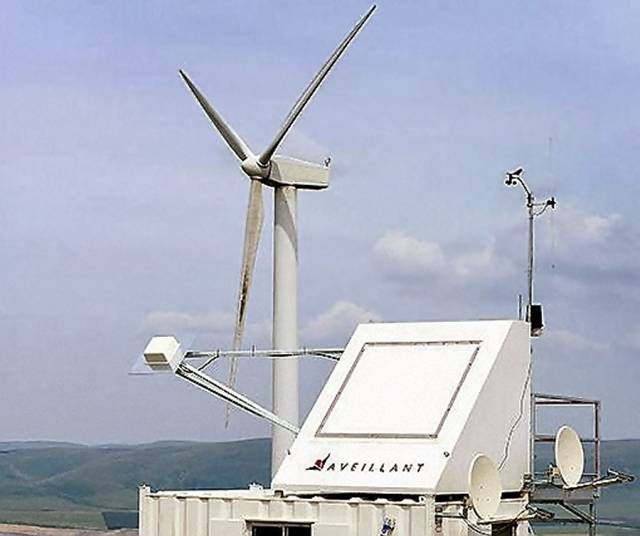
Figure 3: Holographic Radar™ of the company Aveillant Ltd. (Great Britain)[1]
The comparison with image 1 has a special feature here: the various interference lines in holographic photography must be replaced by a large number of receiving channels and a powerful computer. This radar must be equipped with a phased array antenna with digital beam forming. The radar must simultaneously illuminate the entire room to be scanned with its transmitting energy. The receiving antenna contains 100 individual radiators, each with a complete digital receiver. With these data, the computer can calculate a large number of independent antenna diagrams and thus calculate a three-dimensional image.
Because there are no antenna movements, the allocated area can be scanned much more often (up to 4 times per second) than with a normal parabolic antenna (only about every 4 seconds). This makes it much easier to accompany a target, since the target is illuminated practically all the time. A target movement can thus be detected much more easily without having to assign a new target position to a 4 to 5 second old target sign.
Interference from fixed targets can be better suppressed because they are detected in a different receive channel than higher-flying targets. Even the otherwise interfering wind turbines can be suppressed without any problems, since the frequent interrogation allows a much more accurate Doppler spectrum to be captured and very small phase differences to be measured.
However, these calculations require computing power in the range of up to 50 teraflops (50 trillion floating point operations per second).
Sources and ressorces:
- “Holographic Radar™” ist ein eingetragenes Warenzeichen der Firma Aveillant Ltd. (Großbritannien)
- James D. Taylor: ''Ultrawideband Radar. Applications and Design'' CRC Press, 2012, ISBN 9781420089868 S.421 (online preview)