The Large Vertical Aperture Antenna

angle
path to aircraft
or buildings below antenna
are attenuated
Figure 1: Antenna pattern of Large Vertical Aperture Antenna, a Cartesian coordinate system turned by 90 degrees clockwise here

angle
path to aircraft
or buildings below antenna
are attenuated
Figure 1: Antenna pattern of Large Vertical Aperture Antenna, a Cartesian coordinate system turned by 90 degrees clockwise here
angle
path to aircraft
or buildings below antenna
are attenuated
Figure 1: Antenna pattern of Large Vertical Aperture Antenna, a Cartesian coordinate system turned by 90 degrees clockwise here
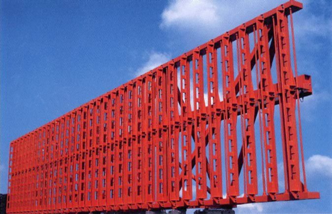
The Large Vertical Aperture Antenna
Large Vertical Aperture (LVA) antennas are often used by secondary radars. An LVA- antenna enables the vertical pattern of the antenna to be shaped. It is a phased array antenna and contains a vertical array of elements (dipoles). The fixed power distribution and phasing to these elements produces the required vertical pattern.
In practice, the LVA antenna will be tilted so that the peak of the beam is at a positive elevation angle. Typically the gain on the horizon will be 4 to 10 dBs down from the peak to achieve a greater cut off rate towards the ground. (Typical cut off rates at the horizon are from 1.5 to 2 dB per degree of elevation, depending upon the antenna tilt.)
Because of the reduced gain at negative elevation angles, the LVA antenna attenuates multi-path signals to and from the ground. This has the following benefits:
- The LVA reduces vertical lobing and so increases the range performance of the secondary radar.
- The LVA reduces the power of multipath signals from ground reflections coming into the antenna at different off-boresight angles from the direct signal. This reduces monopulse azimuth errors.
- The LVA reduces power of interrogations in the direction of buildings and other reflecting surfaces below the antenna. This reduces the likelihood of the reflected interrogations beeing able to produce replies from aircraft at other azimuths and give rise to false plots.


