Waveguide Input/Output Methods

Figure 1: Probe coupling in a rectangular waveguide and its distances to the walls

Figure 1: Probe coupling in a rectangular waveguide and its distances to the walls
Waveguide Input/Output Methods
When a small probe is inserted into a waveguide and supplied with microwave energy, it acts as a quarter-wave antenna. Current flows in the probe and sets up an E field such as the one shown in figure 1. The E lines detach themselves from the probe. When the probe is located at the point of highest efficiency, the E lines set up an E field of considerable intensity. The most efficient place to locate the probe is in the center of the “a” wall, parallel to the “b” wall, and one quarter-wavelength from the shorted end of the waveguide, as shown in figure. This is the point at which the E field is maximum in the dominant mode. Therefore, energy transfer (coupling) is maximum at this point. Note that the quarter-wavelength spacing is at the frequency required to propagate the dominant mode.

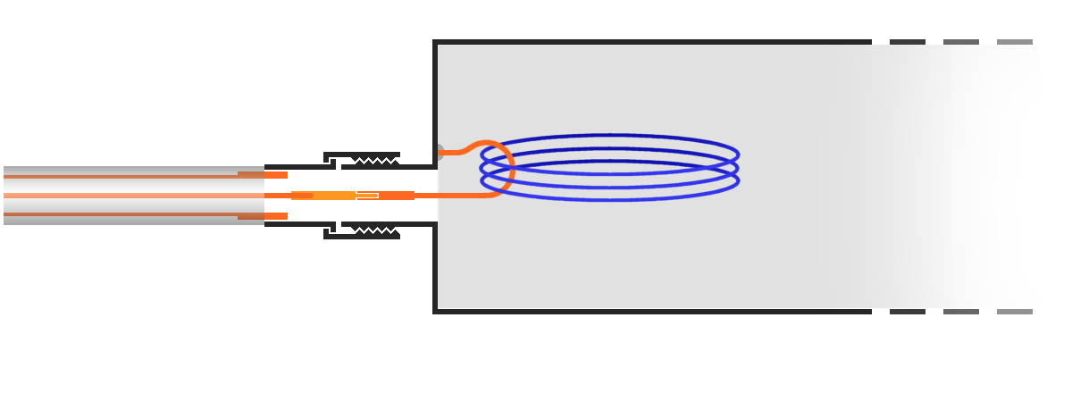
Figure 2: Loop coupling in a rectangular waveguide
By probe coupling in a rectangular waveguide first an E field is produced which causes a H field. Removal of energy from a waveguide is simply a reversal of the injection process using the same type of probe.
In practice is to handle a small problem, however. The probe also should have a good customization for the cable. This means, it also should be long for λ/4! Unfortunately, this measure contradicts with the length of the wall “b”, however. This wall is usually longer than λ/4 only a little.
Because of this the probe gets an additional capacitive reactance. This additional capacity reactance is in the accompanying example created with an opposite screw (as shown in Figure 4). This is advisable to get also a tunable resonant frequency also. The form of the probe widened to to the top strongly causes a greater band with of the probe.

Figure 3: Feeding with a patch antenna mounted on the rear wall of the waveguide.
Loop Coupling in a Waveguide
Another way of injecting energy into a waveguide is by setting up an H field in the waveguide. This can be accomplished by inserting a small loop which carries a high current into the waveguide, as shown in the figure. A magnetic field builds up around the loop and expands to fit the waveguide. If the frequency of the current in the loop is within the bandwidth of the waveguide, energy will be transferred to the waveguide.
For the most efficient coupling to the waveguide, the loop is inserted at one of several points where the magnetic field will be of greatest strength. By loop coupling in a rectangular waveguide first a H field is produced which causes an E field.
Coupling with a microstrip antenna
Modern technologies make it possible that the feed can also be done by a patch- or microstrip antenna. The modern mind is not the patch antenna itself but the possibility of, for example, to accommodate on the back of multi-layer PCB substrate, the entire oscillator circuit. Through the coaxial connector, only the supply voltage is routed in this case.


