Angular Resolution

Figure 1: The distance SA depends on the slant-range
What is the radar angular resolution?
Angular Resolution
Radar angular resolution is the minimum distance between two equally large targets at the same range which radar is able to distinguish and separate from each other.
Angular Resolution as Antenna Parameter
The angular resolution characteristics of radar are determined by the antenna beamwidth represented by the −3 dB angle Θ which is defined by the half-power (−3 dB) points. The half-power points of the antenna radiation pattern (i.e. the −3 dB beamwidth) are normally specified as the limits of the antenna beamwidth for the purpose of defining angular resolution; two identical targets at the same distance are, therefore, resolved in angle if they are separated by more than the antenna −3 dB beamwidth.

Figure 1: The distance SA depends on the slant-range
An important remark has to be made immediately: the smaller the beamwidth Θ, the higher the directivity of the radar antenna. The angular resolution as a distance between two targets calculate the following formula:
.print.png)
.png)
(1)
- Θ = antenna beamwidth (Theta)
- SA = angular resolution as a distance between two targets
- R = slant range aim - antenna [m]
The angular resolution of targets on an analog PPI-scope, in practical terms, is dependent on the operator being able to distinguish the two targets involved. Systems having Target-Recognition features can improve their angular resolution. Cause such systems are able to compare individual Target-Pulse-Amplitudes.
In 3D radars, a resolution in the elevation angle can also be measured. Here, the same method is applicable as in the azimuth resolution. As angle Θ is used the vertical beamwidth then.

beamwidth Θ
between nulls
Figure 2: half-power beamwidth vs. null angle
(half beamwidth between nulls)

beamwidth Θ
between nulls
Figure 2: half-power beamwidth vs. null angle
(half beamwidth between nulls)
Angular Resolution using Lidar
In certain cases (for example, Lidar), it is easier to determine the angular resolution don't use the half-power beamwidth but optical rules. The resolution of an optical system is defined by the angular separation between two similar point-like objects, the main maximum of the image of one point-like object being within the first minimum of the image of the other object.
This definition based on radar means: The angular resolution of radar is defined as the angular distance between the first minimum of the antenna pattern (next to the main lobe) and the maximum of the main lobe (null angle or the half beamwidth between nulls)
To calculate the beamwidth you can use the relationship:
.print.png)
.png)
(1)
- λ = free-space wavelength
- D = aperture dimension
- K = beamwith factor
Assuming a linear phase distribution, each amplitude distribution has a corresponding beamwidth factor, expressed either in radians or in Radiant. The beamwidth factor depends on the antenna type and varies from 0.89 rad (≙ 56 degrees) for an ideal reflector antenna, up to 2 rad (≙ 114 degrees). For the null angle of a synthetic aperture the beamwidth factor is 1.220 rad (≙ 70 degrees).
The null angle thus only refers to half the width of the main lobe. The half-power beamwidth and the beamwidth between nulls relate to the entire width of the main lobe (see Figure 2). Both angles (zero angle and half-power beamwidth) are thus similar in size but not equal. However, the difference in size can be neglected in practice approximately. However, when applying the formula (1), it is necessary to consider the relation of whether the angle used is only half the width of the main lobe or both halves. This confounds since the variable name «theta» is commonly used for all these angles in the literature.
Cross Range Resolution
Due to the computational postprocessing, the synthetic aperture radars (SAR’s) resolution capability has completely different contexts than that of a classical radar with a real antenna. Specifying an angle for the beamwidth is impractical because it cannot be measured but only calculated. In the SAR, a distance is measured perpendicular to the direction of the movement of the radar platform. The resolution in the direction of motion is thus orthogonal to the radar beam and the range measuring and is, therefore, called cross-range resolution. In contrast to the real aperture, the cross range resolution improves with the increase in the half-power beamwidth of the real antenna. The radar will only process echo signals from the object that is detected by the antenna during a flyby in all measurements. There are the more measurement results, the larger the half-power beamwidth of the real antenna. The more single echo signals flow into the processing, the better will be the angular resolution. Since the so-called “footprint” of the radar increases with the distance, the synthetic aperture increases too, and the angular resolution at a larger distance is better than at the close range. This compensates for the deterioration of resolution due to the larger distance. In contrast to the real aperture, the cross-range resolution of the SAR is therefore approximately constant with increasing range.
Angular Resolution using CW Radar

Figure 3: Influence of the distance on the angle resolution.
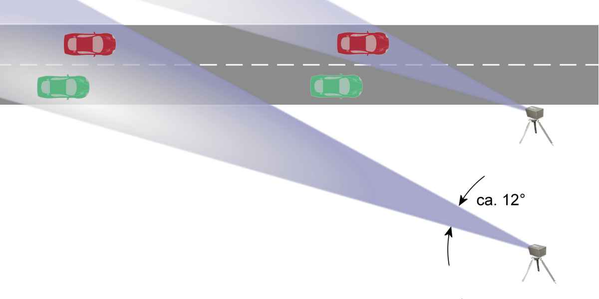
Figure 3: Influence of the distance on the angle resolution.
At short distances using a CW radar extreme accuracies are possible with very little effort. Therefore, such radars are often used for speeds gauges on the road. The angular resolution is determined according to equation (1) by the half-power beamwidth Θ of the antenna and the distance R to the object to be measured.
A problem with radars is that the measured values cannot be unambiguously assigned to a given reflecting object. Depending on the kind of modulation of these FMCW radars, separation of two simultaneously reflecting objects is often not possible. If the distance to the measurement object is large, then the antenna pattern widens. If then two cars are located in the main lobe, a separation is not possible. In this case, the measurement is invalid.
Reference:
- IEEE, “IEEE Standard Radar Definitions,” Radar Systems Panel, IEEE Aerospace and Electronics Systems Society, Report No. IEEE Std 686-2008, 2008.